I'm still a tube design newbie, but lately I've been learning all I could, reading Morgan Jones and Bruce Rozenblit's books, and experimenting with PSpice. I've been playing with a design for an OTL amp using 6C33Cs, and I was hoping that the more knowledgable here would take a look and give me their opinions.
John Broskie's Tube Cad Journal from a few years ago included a partial schematic for an OTL amp he called "Circlotron/Horizontal push-pull amplifier with cross-coupled feedback" which piqued my interest. It uses a 6DJ8 to drive a push-pull pair of 6AS7s, with the cathodes of the 6DJ8 tied to those of the 6AS7 and the output. As he says, "If the output does not follow their cathodes, their cathode-to-grid voltage will change in value as a consequence," and "So what this circuit does is apply a quick, short feedback loop across the 6AS7s. This feedback greatly reduces the output impedance and lowers the distortion of the amplifier."
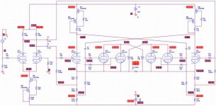
Attached below is the version I've been tinkering with, currently using a 6SN7 (or possibly a 7N7 for its lower capacitances) to drive a quad of 6C33Cs (one parallelled pair for push, one for pull). The preceding gain/phase splitter stage is a long-tailed pair made from a 6SL7 (or 7F7) with a CCS cathode load. Originally I started out with a 12AX7 LTP and 6DJ8 driver, then tried changing the driver to a 5687, and then the 6SN7, which I understand is known for its linearity. However, I was dismayed at seeing all those great parallel lines on the plate characteristics graph getting smushed together at the southeastern end of my load line, so I tried CCS plate loads instead of resistors, which simulates great, but makes my schematic look pretty FET-heavy. As far as I can tell, Miller effect in the 6C33Cs is negligible due to their sub-unity gain. The 100 ohm grid stoppers are just token values at the moment, and the other overly-precise resistor values were chosen to get idle voltages and currents as close to integers as possible.
It's meant to run in class AB1 only. With an 8 ohm (resistive) load, input sensitivity is 1.5 Vp-p, and max output power is 100 W peak. With a 4 ohm load, sensitivity is 1 Vp-p and power is 74 W peak. Bandwidth is within 1 dB from around 7Hz to 90 kHz, and THD is about 0.5%. Of course these are idealistic results with a purely resistive load, but you get the idea.
Does anyone see anything glaringly wrong with this design, with my choice of tubes, or anything else? Are the CCS anode loads a bad idea? I'm very curious to hear any comments you might have, and to learn all I can. Thanks very much.
Aaron T.
(Please view the full-sized schematic here )
John Broskie's Tube Cad Journal from a few years ago included a partial schematic for an OTL amp he called "Circlotron/Horizontal push-pull amplifier with cross-coupled feedback" which piqued my interest. It uses a 6DJ8 to drive a push-pull pair of 6AS7s, with the cathodes of the 6DJ8 tied to those of the 6AS7 and the output. As he says, "If the output does not follow their cathodes, their cathode-to-grid voltage will change in value as a consequence," and "So what this circuit does is apply a quick, short feedback loop across the 6AS7s. This feedback greatly reduces the output impedance and lowers the distortion of the amplifier."
Attached below is the version I've been tinkering with, currently using a 6SN7 (or possibly a 7N7 for its lower capacitances) to drive a quad of 6C33Cs (one parallelled pair for push, one for pull). The preceding gain/phase splitter stage is a long-tailed pair made from a 6SL7 (or 7F7) with a CCS cathode load. Originally I started out with a 12AX7 LTP and 6DJ8 driver, then tried changing the driver to a 5687, and then the 6SN7, which I understand is known for its linearity. However, I was dismayed at seeing all those great parallel lines on the plate characteristics graph getting smushed together at the southeastern end of my load line, so I tried CCS plate loads instead of resistors, which simulates great, but makes my schematic look pretty FET-heavy. As far as I can tell, Miller effect in the 6C33Cs is negligible due to their sub-unity gain. The 100 ohm grid stoppers are just token values at the moment, and the other overly-precise resistor values were chosen to get idle voltages and currents as close to integers as possible.
It's meant to run in class AB1 only. With an 8 ohm (resistive) load, input sensitivity is 1.5 Vp-p, and max output power is 100 W peak. With a 4 ohm load, sensitivity is 1 Vp-p and power is 74 W peak. Bandwidth is within 1 dB from around 7Hz to 90 kHz, and THD is about 0.5%. Of course these are idealistic results with a purely resistive load, but you get the idea.
Does anyone see anything glaringly wrong with this design, with my choice of tubes, or anything else? Are the CCS anode loads a bad idea? I'm very curious to hear any comments you might have, and to learn all I can. Thanks very much.
Aaron T.
(Please view the full-sized schematic here )
Attachments
Circlotron OTL design
Hallo Aaron,
the biasing of your OTL design is very critical. That is not a particular problem of your design. That is typical for almost all circlotron based OTL-designs from my knowledge. The 6C33C has a large variation of anode current during warm-up. And after large amplified signal (i.e. dynamic peak in a classic Symphony) this anode current will have another value than before. This causes a large unsymmetry of the bridge and a rather high DC voltage occurs at the load (loudspeaker). Another problem is the runaway of the working points of the output tubes (6C33C). Like with the Graaf GM-20 circuit the stabilizing of the DC working point does not operate sufficiently well. Graaf selects the 6C33C tubes quite hard for lowest drift of anode current and best matching. You will need about 40 tubes to find 4 pieces which might work. But there is no guarantee that your amp will work after 50 hours of operation (if it or your loudspeaker survives this time span...). So, all in all it is not recommendable from my point of view to build such an amp.
Greatings Arcolette
DC Servo
I have heard of this bias or operating point runaway for 6C33 before. A simple way to fix this would be to use a couple of Op. Amp. DC servos on the output tubes. These just monitor the DC current levels and control the DC bias levels, the audio signal is still AC coupled from the tube drivers. A little more tricky to sample the current in the Circlotron configuration, maybe have to use instrumentation differential amps to measure floating voltage on a small sampling resistor. Unfortunately the sampling resistors raise output impedance some.
Another way would be to use a couple of center tapped inductors (or just one, if you can find one with two center tapped windings) and just one non-floating power supply. Inductor 1 connnects across the 6C33 plates and inductor 2 connects across the load (or cathodes) and gets its center tap grounded. The power supply connects between the two center taps. Current sampling resistors can be put into the separate wires forming the grounded center tap. Then put the final power supply filter caps across the inductor ends in the same way the floating power supplies would have been connected. By connecting the caps to the non grounded end of the sampling resistors, the resistors will be deleted from the audio current path, so won't affect output impedance. And, the sampling resistors will have one end grounded for easy use with a couple of DC bias servo Op. Amps.
The inductors will have balanced DC currents if the DC servos are working correctly, so no air gap required for the inductors. The all-in-one inductor design has to have the phasing between windings correct. Have to make sure the inductor(s) have enough inductance to avoid loading the amplifier and heavy enough wire to handle the DC currents.
Don
in this case this thread could be of interest
http://www.diyaudio.com/forums/tubes-valves/142528-graaf-gm20-mods-help.html
http://www.diyaudio.com/forums/tubes-valves/142528-graaf-gm20-mods-help.html

You might want to read my 6C33 otl saga (you can find it on my website) many of the issues raised by others on this thread can be dealt with by careful burn-in and aging of the 6C33 before you put them into service.
There are a number of members here who have been running 6C33 based circlotrons for many years without difficulty. It is all down to design and properly selecting the output tubes. Hopefully one of these guys will weigh in and give you some guidance.
I never observed the odd dynamic behavior Arcolette describes in his post, and bias drift was most significant in the first 15 minutes of operation, and I think can easily enough be compensated for in a good design without the use of a bias servo.
Cathode follower or source followers direct coupled to the grids of the 6C33 seem to work better in my experience as they do draw some grid current even at modest power levels. I would try to keep things simple, I think you have over complicated things. (I certainly did in my design which is why it is not available today)
A few key points:
Filament currents are extremely high and will destroy most socket contacts, some mil surplus Soviet era sockets are rugged enough.
Convection cooling around the sockets and tube bases will improve tube and socket life.
Keep anode dissipation to 45W or less.
Higher currents at lower plate voltages seem to work better. IMHO don't go over 140V, and 110 - 120V is probably most reasonable.
100W into 4 ohms is unrealistic even with 4 x 6C33, ok into 8.
Burn in all output tubes for a minimum of 48hrs in a jig built for the purpose. Start by running just the filaments for 30 minutes or longer and then apply bias and plate voltage in that order. Ramp up the plate current over a couple of hours to provide 45W of dissipation. Make sure whatever you do is safe!
A few key points: [re: OTL power amp using 6c23 tubes]...
"Keep anode dissipation to 45W or less.
Higher currents at lower plate voltages seem to work better. IMHO don't go over 140V, and 110 - 120V is probably most reasonable. ...kevinkr"
100W into 4 ohms is unrealistic even with 4 x 6C33, ok into 8....
Hi there: As mentioned by "kevenkr" in the above post, with 110 to 120v dc for the B+, a simplified SS diode power supply would be possible, eliminating the load of iron transformer for the four 6c23's, cost and space saving? (6.3v filiment transformer(s) would still be needed).... regards, Michael
6c33-design-comments
Hi Aaron,
did you already see this thread? Might be interesting to you....
http://www.diyaudio.com/forums/tubes-valves/94020-6c33-design-comments.html
This thread tells also a lot about experience with 6C33 Circlotron amps...
I have built one, not easy and certainly not a beginner's project, but I use it since several years now regularly without any bigger problems - but surveillance of the bias currents is recommended
all the best
Uli
If you really want to build an OTL, do yourself a favor and avoid the 6C33. Its a great sounding tube, but if you don't drink the cool-aid from the experience posted above, you will toast the sockets, and the tubes themselves are not exactly cheap.
The 6AS7 is a lot easier to set up and overall less expensive, certainly more reliable.
If you do stick to the 6C33s, I strongly recommend inserting some 10watt 3 ohm resistors in series with each cathode! The tubes will hold up better and you will reduce distortion as well. I would also consider installing a fuse in series with each cathode, about 1.5A for protection against arcs in the tubes.
**Do not** capacitively couple to a the grid of a 6C33. If you do you will be dealing with getting bass and transparency out of the unit and juggling that against bias stability. IOW you will be trying to put the smallest cap in the unit that still plays bass and is transparent, and when you reach the limits there then the bias network will get 'reworked' to a higher impedance to allow the timing constant to play out. Its a battle you can't win! Using a cathode-follower driver direct-coupled to the grids eliminates this problem.
- Status
- This old topic is closed. If you want to reopen this topic, contact a moderator using the "Report Post" button.
- Home
- Amplifiers
- Tubes / Valves
- Seeking advice on "Circlotron" cross-coupled feedback OTL design