I started my new project to go with my Peter Daniel's Gain clone. The GC is great, but I want some more flexibility with inputs selection, Remote control and a little bit of nice, warm tube touch.
This project is also my first complete Processor controlled preamp. After searching I decided on the BottleHead ForePlay preamp. It use basicly the same topology but uses DC filament.
ALBQ, an other member of this great forum was of great help on this project. See his excellent website on his own preamp at:
http://mywebpages.comcast.net/gillespie147/12AU7-Preamp.html
I also decided to implement right away most of the mods that I found on the ForePlay.
The Features list is:
Frame:
Nice Oak tainted Red Mahogany by MinWax excellent product.
Top and bottom Plates are steel, 1/8 thichness, that I salvaged from a 19" rack shelf (very strong)
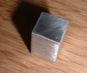
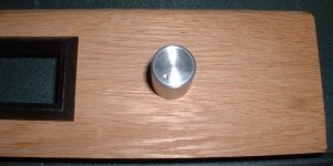
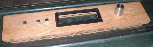
DIY Volume knob and Function buttons made of aluminium
Vibration Control:
Vibration absorbant sheet glued on top & bottom plates.
Rigid steel sub chassis to hold inside parts.
Transformers mounted on rubber bushing.
Arrowhead used as decoupling points.
Wood Capacitors Bracket holder, you'll will see.
Nitrile o-rings on Tubes
Circuit:
Processor Controlled with IR Sony compatible remote control
LCD Display with BackLight.
Serial port to change BasicStamp Program externally.
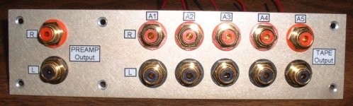
4 Inputs, 1 REC Output, 1 Output
Motorized ALPS Volume Control
Completly separate Control Power Supply with noise filtering
Front Panel Function buttons: ON/Standby, Channel Selection, Mute
Power Up and Down sequence to protect tube
Automatic 45-sec. warmup mute. Automatic brown-out mute.
Main Power switch with On steady / Flash Standby Led
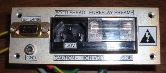
IEC-standard three-pin socket at the rear, allowing custom A.C. cords to be used. Includes an integrated noise filter.
Extensive GND layout with Power, Audio and Control GND united at a Star Gnd.
Safety GND and RC GND Loop Breaker.
Mods
Camille Cascode Constant Current Source upgrade
Parts Upgrade
Relays Input selection and Mute. COTO Sealed relays with eletrostatic shield to reduce crosstalk.
RCA gold Plated connectors.
Magnet Wire GND wire
Teflon coated high purity copper wire
Bigger Hammond HV, filament transformer. So I can use different tube
Azuma 9 pins Gold-Ceramic socket
Dale RN60D Film Resistor for small signal and Xicon Power Carbon Film Resistors
Panasonic TS-Type 105C capacitors in Power supplies.
Panasonic FC-Type decoupling caps.
Wima MKP bypass caps.
ElectroCube Film coupling cap.
Fast Recovery Diode with snubber for filament and HV supplies.
DIY AC Power Cord with Hubell connectors
This project is also my first complete Processor controlled preamp. After searching I decided on the BottleHead ForePlay preamp. It use basicly the same topology but uses DC filament.
ALBQ, an other member of this great forum was of great help on this project. See his excellent website on his own preamp at:
http://mywebpages.comcast.net/gillespie147/12AU7-Preamp.html
I also decided to implement right away most of the mods that I found on the ForePlay.
The Features list is:
Frame:
Nice Oak tainted Red Mahogany by MinWax excellent product.
Top and bottom Plates are steel, 1/8 thichness, that I salvaged from a 19" rack shelf (very strong)
DIY Volume knob and Function buttons made of aluminium
Vibration Control:
Vibration absorbant sheet glued on top & bottom plates.
Rigid steel sub chassis to hold inside parts.
Transformers mounted on rubber bushing.
Arrowhead used as decoupling points.
Wood Capacitors Bracket holder, you'll will see.
Nitrile o-rings on Tubes
Circuit:
Processor Controlled with IR Sony compatible remote control
LCD Display with BackLight.
Serial port to change BasicStamp Program externally.
4 Inputs, 1 REC Output, 1 Output
Motorized ALPS Volume Control
Completly separate Control Power Supply with noise filtering
Front Panel Function buttons: ON/Standby, Channel Selection, Mute
Power Up and Down sequence to protect tube
Automatic 45-sec. warmup mute. Automatic brown-out mute.
Main Power switch with On steady / Flash Standby Led
IEC-standard three-pin socket at the rear, allowing custom A.C. cords to be used. Includes an integrated noise filter.
Extensive GND layout with Power, Audio and Control GND united at a Star Gnd.
Safety GND and RC GND Loop Breaker.
Mods
Camille Cascode Constant Current Source upgrade
Parts Upgrade
Relays Input selection and Mute. COTO Sealed relays with eletrostatic shield to reduce crosstalk.
RCA gold Plated connectors.
Magnet Wire GND wire
Teflon coated high purity copper wire
Bigger Hammond HV, filament transformer. So I can use different tube
Azuma 9 pins Gold-Ceramic socket
Dale RN60D Film Resistor for small signal and Xicon Power Carbon Film Resistors
Panasonic TS-Type 105C capacitors in Power supplies.
Panasonic FC-Type decoupling caps.
Wima MKP bypass caps.
ElectroCube Film coupling cap.
Fast Recovery Diode with snubber for filament and HV supplies.
DIY AC Power Cord with Hubell connectors
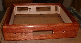
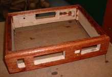
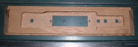
First, the wood frame
The frame is made of oak. I cutted all the holes first. Used a router to cut in the front panel to let place for the LCD display, Switches PCB and motorized pot. Four nice coats of Red Mahogany Red MinWax Vernish/Taint covering. Here it is, not too bad.
The frame is made of oak. I cutted all the holes first. Used a router to cut in the front panel to let place for the LCD display, Switches PCB and motorized pot. Four nice coats of Red Mahogany Red MinWax Vernish/Taint covering. Here it is, not too bad.
Attachments
The other plate is what I called the AC Outlet plate. The IEC noise filter with integrated fuse socket is mounte there. It contains also the Processor serial port and the Frame GND screw. This screw is connected to the AC safety gnd. Two wires go from there and connect to the top and Bottom steel plates for safety.
Then it goes to an RC Gnd loop killer 10R,3W and 0.1uF, 400V, X2-Type cap.
Then the other point of the RC goes to the preamp star GND point. These GND are not directly conencted to the frame (safety gnd).
Then it goes to an RC Gnd loop killer 10R,3W and 0.1uF, 400V, X2-Type cap.
Then the other point of the RC goes to the preamp star GND point. These GND are not directly conencted to the frame (safety gnd).
Attachments
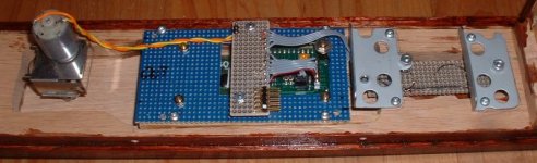
Inside, i needed to hold the tube supplies caps in place. I also need to find a place for the relay assy. These relays turn on the filament power, then the HV in sequence under processor control.
I also wanted to keep the AC on the right (view from the bottom) and near the AC outlet. I'll keep the audio on the left. The control will be on the right near the front.
Instead on drilling a lot of holes in the top plate, which is least nice, I salvaged a steel sub frame from an old computer monitor. I cut the frame according to my need and install it using just 3 screws on the top. Then I'll use this frame to mount the reast of the big stuff. This frame is also quite rigid.
Attachments
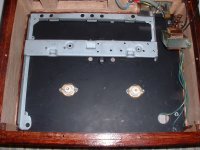
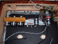
Here is the sub-frame with everything mounted on it. You can see the 3 bigs caps on the left used by the HV Pi-Filter. A nice wood backet hold them firmly in place and kill vibration. In the center, just over where the Tube Supply transfo will be located are the soldering bars for the transfo wire and the discrete fast-recovery diode bridge. I'll use the MUR860, 600V, 8A diodes.
Then on the right, you can see the relays assy mounted vertically and the two caps used for the filament supply. On the back, you see a small blue isolated stand-off. That will be the star gnd.
Then the subframe was all cover with vibration absorbing sheet.
Then on the right, you can see the relays assy mounted vertically and the two caps used for the filament supply. On the back, you see a small blue isolated stand-off. That will be the star gnd.
Then the subframe was all cover with vibration absorbing sheet.
Attachments
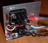
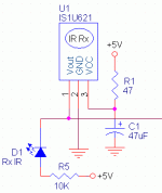
Here the socket side of the Relay Assy. It contains 2 relays, Potter & Brumfield, K10P-11015-12, operated in 12Vdc. They are mounted on sockets. I connected the 2 DPDT contacts in parallel to reduce the contact resistance. These are tought, industrial relays, gold plated contacts. They are overkill but I had them from an other project. The contacts are rated 240V. Perfect for the 160V HV I'll use.
They are driven by the control supply. I use a 14Vac transfo to supply the 5V logic supply. It give me 18V raw dc voltage to use with the relays. A simple res. 75R, 1/2W drop this voltage to 12V. I drive the relays using small 2N2222A transistor from the processor. The schematic will follow soon.
They are driven by the control supply. I use a 14Vac transfo to supply the 5V logic supply. It give me 18V raw dc voltage to use with the relays. A simple res. 75R, 1/2W drop this voltage to 12V. I drive the relays using small 2N2222A transistor from the processor. The schematic will follow soon.
Attachments
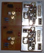
Here my own version of the Camille Cascode Constant Current Source PCB that I will use to biais the tubes. I combined the informations on these two sites to get the circuit working  ,
,
See:
A good tutorial on how to assemble the C4S Foreplay option:
http://home.att.net/~joemacjr/diyproject/anticipation_tutorial.html
and this excellent discussion on the C4S protections:
http://www.siteswithstyle.com/VoltSecond/C4S_extended_volts_and_amps/C4S_extended_volt_and_amps.html
Take note that the original Anticipation circuit is a BottleHead Desing and their property. Since I never saw their PCB, I cannot comment on how it to compare mine.
,See:
A good tutorial on how to assemble the C4S Foreplay option:
http://home.att.net/~joemacjr/diyproject/anticipation_tutorial.html
and this excellent discussion on the C4S protections:
http://www.siteswithstyle.com/VoltSecond/C4S_extended_volts_and_amps/C4S_extended_volt_and_amps.html
Take note that the original Anticipation circuit is a BottleHead Desing and their property. Since I never saw their PCB, I cannot comment on how it to compare mine.
Attachments
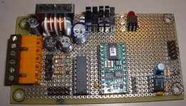
Here the Processor PCB Assy. It contains the Basic Stamp Processor, the logic and relay power supplies and the drivers ULN2803 and small transistors to drives the different relays.
The schematic follows. The Code is still in the prototype stage. I'll post it as soosn as possible...
Bye...
SB
The schematic follows. The Code is still in the prototype stage. I'll post it as soosn as possible...
Bye...
SB
Attachments
- Status
- This old topic is closed. If you want to reopen this topic, contact a moderator using the "Report Post" button.
- Home
- Amplifiers
- Tubes / Valves
- My ForePlay Processor Controlled Preamp