Hi everyone. I've working on that project part time. It is almost done now.
The switches are well integrated in the code. The code is almost completed. I'm still working to improve the volume motor control. I what a smooth, continuous operation. I'll post the code when completed.
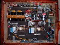
I completed the analog assembly. Here the power distribution with the small control supply transformer. At the AC input there is an EMI filter with fuse integrated. The main supply goes to the main power switch and the control transformer. Then 2 relays control the filaments and HV in sequence at power up and power down.
The switches are well integrated in the code. The code is almost completed. I'm still working to improve the volume motor control. I what a smooth, continuous operation. I'll post the code when completed.
I completed the analog assembly. Here the power distribution with the small control supply transformer. At the AC input there is an EMI filter with fuse integrated. The main supply goes to the main power switch and the control transformer. Then 2 relays control the filaments and HV in sequence at power up and power down.
Attachments
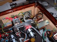
GND is very important. Here the safety GND point. Directly connected to AC earth gnd it connect to both top and bottom metal covers. It connects also to the rear AC plate on a screw marked GND. Then it goes to a small junction point throught a gnd loop breaker, 10R, 3W resistor and a 0.1uF, 400V, X2 type in parallel.
Attachments
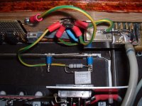
Then all the GND inside the preamp connect at one point only, the star gnd on the left. This this point connects directly to earth gnd throught the GND loop breaker. The GND are all run separately:
HV and Filament supplies power GND, right and left audio channels, audio gnd of the jacks on the back.
That note that the digital gnd is not connected anywhere to the preamp gnd. The digital section runs on a completly separate supply.
HV and Filament supplies power GND, right and left audio channels, audio gnd of the jacks on the back.
That note that the digital gnd is not connected anywhere to the preamp gnd. The digital section runs on a completly separate supply.
Attachments
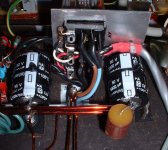
Both supplies use MUR860 soft recovery diodes with caps snubber. I used WIMA MKP small caps on the filament and X2 HV type on the HV section. Everything is point to point. I'm using lacque coated good grade copper wire. This wire is the same used to rewire motor for greater efficiency. It is hi conductance copper from a electric motor shop.
The filament rectifier bridge is on the front, the HV is on the back. The power transformer sits just under the bridges.
The filament rectifier bridge is on the front, the HV is on the back. The power transformer sits just under the bridges.
Attachments
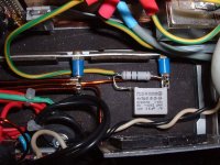
This is the HV filter section. I'm using a three section PI filter, with 330uF, 400V and 1K resistors. A 120K bleed resistor is at the end with a ERO KP1832 bypass cap that I had in stock (check on the left). Check my "wood vibration absorber' for the caps 
The nice power resistors are from a surplus store. Not needed but nice
The nice power resistors are from a surplus store. Not needed but nice
Attachments

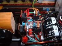
The filament filter with the two 3300uF caps well mounted on the metal frame. I added an ERO MKC1863 1.5Uf as bypass cap.
The power transfo used Hammond 269AX, can provide enough current to supply 6N1P tubes, 6.3V, 2A
You can also see the base of the releays mounting plate.
The power transfo used Hammond 269AX, can provide enough current to supply 6N1P tubes, 6.3V, 2A
You can also see the base of the releays mounting plate.
Attachments
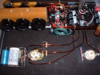
This is a complete channel. Missing are the wires from the volume pot and the output coupling cap. I will use a NOS paper in oil from Sprague. I'll do some listening, and I may use a bypass with an ERO KP1832 cap.
Check the power distribution with the nice wires, gnd, filament and HV supply. I used massive bypass on the 470uF, Panasonic decoupling cap on the cathode resistor. Electrolytic cap at this location are reported to add to the sound. The bypass are a try to improve on that, Still need to listen to it. I used what I had in stock, 2.5uF Cornell Dubiller poly cap and 0.047uF ERO KP1832.
Check on the left of the socket.
I also added ferrites on the filament wire to reduce radio induction if possible, check the two small beads on the wire.
That is all for now.
Attachments
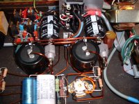
I just added two PI filters on the filament supply of each tube. The filament supply was 6.7V and a bit too noisy at almost 300mV of ripple
So I added a 0.2 ohm resistor (nice power resistor that I had in stock) and a big 10,000uf cap for each tube. The voltage at the tube drops to a nice 6.3V and 60mv of ripple, much better
So I added a 0.2 ohm resistor (nice power resistor that I had in stock) and a big 10,000uf cap for each tube. The voltage at the tube drops to a nice 6.3V and 60mv of ripple, much better
Attachments
Listening Session
My first lsitening was very interesting. The high were sweet and the bass was good too, but the medium had some coloration to it, in particular female voices. I was using a sole AuriCap coupling cap at the preamp output.
There was also the noise issue. There was two problems. I could here a rather loud buzz noise when activating the volume motor control. There was also a hiss sound in the background that reduce the dynamic of music.
I solved the two noise problems at the same time. I ground the case of the potentiometer/pot to the chassis ground. The hiss is just gone and the motor buzz can be eared only at high volume. I can live with that, no problem.
Then I installed the NOS Sprague coupling Caps instead of the AuriCap I had (Thanks Robert) and I can just say WOW!!!
The sound now is just great. Any coloration on voices is gone. The sound is just pure and liquid. The music timing just sing.
I couldn't believe the sound that can have just one cap. This NOS Sprague cap just blow the AuriCap to the sky
I listen to it all evening. Patricia Barber in SACD is cool. Return to Forever-Romantic Warrior punch and rock. Greats recordings just stand out. Chris Botti-Night Sessions is liquid and sexy.
Ayreon-Human equation bring down the house. My Naim CD Sampler with great acoustic recordings lovely. Steely Dan-Two Against Nature rocks, what a great pop reording. Diana Krall-Live in Paris swings. Gary Willis-No sweat, what a great bass player.
The voices are clear and well defined. Small details everywhere. It really sings.
Real music. This is the best preamp I ever built. I can wait to install CSS option and see what changes it will bring, for the better I hope
Bye...
My first lsitening was very interesting. The high were sweet and the bass was good too, but the medium had some coloration to it, in particular female voices. I was using a sole AuriCap coupling cap at the preamp output.
There was also the noise issue. There was two problems. I could here a rather loud buzz noise when activating the volume motor control. There was also a hiss sound in the background that reduce the dynamic of music.
I solved the two noise problems at the same time. I ground the case of the potentiometer/pot to the chassis ground. The hiss is just gone and the motor buzz can be eared only at high volume.
I can live with that, no problem. Then I installed the NOS Sprague coupling Caps instead of the AuriCap I had (Thanks Robert) and I can just say WOW!!!
The sound now is just great. Any coloration on voices is gone. The sound is just pure and liquid. The music timing just sing.
I couldn't believe the sound that can have just one cap. This NOS Sprague cap just blow the AuriCap to the sky
I listen to it all evening. Patricia Barber in SACD is cool. Return to Forever-Romantic Warrior punch and rock. Greats recordings just stand out. Chris Botti-Night Sessions is liquid and sexy.
Ayreon-Human equation bring down the house. My Naim CD Sampler with great acoustic recordings lovely. Steely Dan-Two Against Nature rocks, what a great pop reording. Diana Krall-Live in Paris swings. Gary Willis-No sweat, what a great bass player.
The voices are clear and well defined. Small details everywhere. It really sings.
Real music. This is the best preamp I ever built. I can wait to install CSS option and see what changes it will bring, for the better I hope
Bye...
I did some measurements. Here the Unofficial Specs
Vin Max: 1.4Vrms
Vout Max: 14.6Vrms
Gain Voltage: 10 or 20dB
Zout: 600 ohms
BandWidth (-3dB, ref. 1Khz, 1V): 2Hz - 70Khz
Distorsion (in 10Kohms, 1V): 0.40% (1Khz), 0.38% (20Khz)
Noise (Input gnd): 0.2mv (min. Volume), 0.8mv (max. Vol.),
Crosstalk:
-between input channels (Ref 1V): -78dB (1Khz), -65dB (20Khz)
-between output channels: <70dB (noise floor, 1Khz), -62dB (20Khz)
Very good indeed
- Status
- This old topic is closed. If you want to reopen this topic, contact a moderator using the "Report Post" button.
- Home
- Amplifiers
- Tubes / Valves
- My ForePlay Processor Controlled Preamp