I recently purchased a home-brew amp here in Santiago and I need some help to get it up and running. I suspect that it is a stereo version of the Mullard 5/20 design. The tube layout is GZ34 (2), EL34 (4), EF86 (2), and 12AX7 (2). It is hefty (35 lbs) spaciously laid out on a 21"x 9" chassis. I brought it up on a variac and got a loud, high-pitched screech from the speakers. What additional information is needed to diagnose the amp? Where do I begin to look?
Thanks for any help.
Bill
Thanks for any help.
Bill
SY said:Check the power supply first. You can disconnect the power stages and power up the supplies with a dummy load and see if they're functioning properly.
How old is the amp? If it's a veteran, plan on replacing all the electrolytic caps and the tubes.
I'm not sure how old it is, but it has obviously been around for a while. A label inside the chassis indicates that the builder was a professional, since it reads "Juan A. Zahbla V. Radio Técnico. Ex-Laboratorista, S. Karlson, Brasil". But the amp has been through other, more and perhaps less skilled hands. Most of the resistors and many of the caps look new. But the two multi-section cans look very old and were sourced in Germany.
The speaker taps contain only a ground and hot tap per channel, and I'm not sure what the impedance for them is. Any way I can check? How do I disconnect the power stages and power up with a dummy load? How do I know if they are functioning properly? Thanks for your patience; you can see that you are dealing with novice.

Tube amps are different than transistor amps in that they carry a MUCH greater shock hazard. If you don't have experience working with these voltages, make sure you do this under supervision. Death is very permanent.
That said, you can estimate that the output stage will draw about 100 ma per channel at idle. The nominal B+ will be something like 400-450 volts. If you can't figure out how to calculate the resistance and power of a dummy load from this information, and how to disconnect the output stages and substitute the dummy load, you'd really, really do yourself a favor by not digging around in there without a seasoned tube veteran standing next to you.
SY said:
Tube amps are different than transistor amps in that they carry a MUCH greater shock hazard. If you don't have experience working with these voltages, make sure you do this under supervision. Death is very permanent.
That said, you can estimate that the output stage will draw about 100 ma per channel at idle. The nominal B+ will be something like 400-450 volts. If you can't figure out how to calculate the resistance and power of a dummy load from this information, and how to disconnect the output stages and substitute the dummy load, you'd really, really do yourself a favor by not digging around in there without a seasoned tube veteran standing next to you.
Thanks for the warning. Unfortunately, we are talking 3rd world here, with no "seasoned tube veterans" in sight (imagine a city with 2 million inhabitants without a single tube supplier or vintage equipment repair shop) and the only source of components or help being the internet.
I have nothing against Santiago when the smog goes away after a rain. Then you get a nice view of the mountains. Besides, there is decent wine reasonably priced. As for a "a seasoned tube veteran standing next to you", Apparently mistakenly, I was under the impression that is precisely what this forum is about.
The problem is that a seasoned electronics engineer would only need to glance at your amplifier for a couple of seconds to spot something glaringly dangerous. If you are able to post some photographs of the inside of your amplifier, that would be very helpful.
The screech sounds like positive feedback. Have the output transformers been replaced? Is there evidence of fresh soldering? Does it definitely screech out of both channels?
The Mullard 5-20 circuit is published all over the place. A web search would probably find it.
The screech sounds like positive feedback. Have the output transformers been replaced? Is there evidence of fresh soldering? Does it definitely screech out of both channels?
The Mullard 5-20 circuit is published all over the place. A web search would probably find it.
Try this:
1) with the amp unplugged and disconnected, put a ~100ohm resistor temporarily across the high voltage capacitors (from + to - of each) to discharge the high voltage. You might also want to read the safety thread in the forum...
2) Then have a look at the output transformer connections. You will see two wires that go to the speaker connectors for each channel ( the secondary of the transformer). The positive speaker terminal will have another wire to a resistor which will go back to the preamp stage. find the value of this resistor.
3) disconnect this wire for each channel and tie it off (use some tape or something) temporarily.
4) Try bringing the amp up on a variac again, see if it squeals.
5) If it is quiet, then try reversing the output transformer secondary leads and reconnecting the resistor.
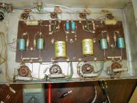
Thanks very much for the information. I'll get to work on it. Meanwhile, I think I need to better understand what kind of beast I am looking at here. Because of the tube complement, I assume it is a Mullard 5/20 design. But looking at the schematic for that amp and the parts list, I see some significant differences. Three of the EL34 output tubes have a 500 ohm cathode bypass resistor and one has a 700 ohm. Each of these tubes has a .1µf 1000V oil cap connected to pin 6. Two of the output tubes have a strange component mounted on on the base. I have attached a couple of pictures. Hopefully, someone can tell me what I'm looking at here.
Thanks.
Thanks.
Attachments
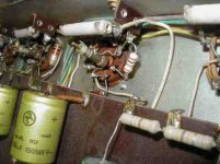
Looking at the components, I'd say it's late 60s or early 70s, and possibly German. It has plenty of Mullard/Philips blue electrolytic cpacitors and C296 polyester coupling capacitors (thos mustard coloured things), but those large yellow electrolytics look German. Also it has a DIN socket, and since the Germans invented DIN, they were the only ones who were really keen on it.
I'd guess that the 700 Ohm resistor is a mistake, and should be 500 Ohm. Check to see if the soldering looks fresher. I couldn't quite see which pin numbers each end went to? Even if it is wrong, it's not the cause of the screeching. You have an awful lot of small valves there. It's highly likely that this amplifier was built as a public address amplifier, and that it has microphone inputs. You need a lot of gain for a microphone, and it's possible that one (or more) of the valves has become microphonic and is causing acoustic feedback. You should be able to test this by turning the volume down. If the screech goes away, it's not a power amplifier problem.
I'd guess that the 700 Ohm resistor is a mistake, and should be 500 Ohm. Check to see if the soldering looks fresher. I couldn't quite see which pin numbers each end went to? Even if it is wrong, it's not the cause of the screeching. You have an awful lot of small valves there. It's highly likely that this amplifier was built as a public address amplifier, and that it has microphone inputs. You need a lot of gain for a microphone, and it's possible that one (or more) of the valves has become microphonic and is causing acoustic feedback. You should be able to test this by turning the volume down. If the screech goes away, it's not a power amplifier problem.
The 10W wire-wound resistors go from pin 8 to ground. Each output tube socket has a 1K one watt resistor from pin 4 to ground and a 2.2K one-half watt resistor from pins 5 to 6. The positive pole of a 50µF cap goes to pin 8 of the EL34 tubes and a .1µF 1000v cap goes to pin 6.
I'm not sure about this being intended as a public address amp, given that it is stereo. The valves that it has (included the 2 GZ34) are what would be expected in order to mount two mono 5/20 amps on one chassis. The former owner tells me that it didn't have the screech until after he tried to remove the DIN input, thinking of installing 2 RCA plugs and then gave up on the idea and re-installed the DIN. Maybe he got the wiring wrong. Is there a way to check?
I'm not sure about this being intended as a public address amp, given that it is stereo. The valves that it has (included the 2 GZ34) are what would be expected in order to mount two mono 5/20 amps on one chassis. The former owner tells me that it didn't have the screech until after he tried to remove the DIN input, thinking of installing 2 RCA plugs and then gave up on the idea and re-installed the DIN. Maybe he got the wiring wrong. Is there a way to check?
Hi Bill,
I have got in at the tail end of this conversation, but find it of interest as I already have two Mullard 5-20 Amplifiers and I am busy constructing another two, purely for the fun of it.
The loud screeching seems to indicate that the feedback path is positive, thereby causing howling, instead of being connected for Negative Feedback. This cannot just happen by itself, it would appear that if this is the cause that someone has inadvertently swapped around the feedback path from the output transformer secondary. Try reversing these leads, or even disconnecting them, for a test. Be aware that if you do disconnect them, your amplifier would be about 4-5 times more sensitive.
The Cathode resistors should be 470-ohm components, 5w wire-wound resistors. These are shunted by 50MF electrolytics. The screen grid at Pin 4 does indeed have a 1000-ohm resistor (to prevent oscillation) and these should be connected as close as to Pin 4 as possible. But they do not go to ground - they go to the SG tap on the output transformer. You should measure a potential of about 435V DC on Pin 4. Pin 5 is the control grid (i.e. "input") of the EL34, and has a 2200-ohm resistor connected to the junction of the 0.5MF coupling capacitor & 470,000-ohm grid resistor. By the way, you'd be well advised to check these capacitors for leakage, rather replace them if there is any doubt. The other side of the 470K resistor goes to earth (ground). Pin 6 of the EL34 is a "No-Connection" pin, and may be used as an anchor for something else.
If you remove the EF86 valve/s, does the squeling go away? Be wary of high voltages around the filter caps, they store plenty of voltage even when the amplifier is disconnected.
Please let me know if I could assist further...
-Eric
Family_Dog said:Hi Bill,
I have got in at the tail end of this conversation, but find it of interest as I already have two Mullard 5-20 Amplifiers and I am busy constructing another two, purely for the fun of it.
Hi, Eric,
I'm very grateful for your response and encouraged that you think well enough of this amp's design to have 4 of them. Do yours have the pair of rectifier tubes as well? I'm not sure why two were used on mine; I see only one rectifier on other stereo amps. What OPTs do you use?
The loud screeching seems to indicate that the feedback path is positive, thereby causing howling, instead of being connected for Negative Feedback. This cannot just happen by itself, it would appear that if this is the cause that someone has inadvertently swapped around the feedback path from the output transformer secondary. Try reversing these leads, or even disconnecting them, for a test. Be aware that if you do disconnect them, your amplifier would be about 4-5 times more sensitive. [/B]
You don't have to look far to discover the inadvertant swapper (says he, contritely). When I disconnect the leads, I don't get the howling. But the amp is way too sensitive. I have a CD player with a volume control contected for testing the amp, and even with the volume way down, it is easily overloaded.
The Cathode resistors should be 470-ohm components, 5w wire-wound resistors. These are shunted by 50MF electrolytics. The screen grid at Pin 4 does indeed have a 1000-ohm resistor (to prevent oscillation) and these should be connected as close as to Pin 4 as possible. But they do not go to ground - they go to the SG tap on the output transformer. You should measure a potential of about 435V DC on Pin 4. Pin 5 is the control grid (i.e. "input") of the EL34, and has a 2200-ohm resistor connected to the junction of the 0.5MF coupling capacitor & 470,000-ohm grid resistor. By the way, you'd be well advised to check these capacitors for leakage, rather replace them if there is any doubt. The other side of the 470K resistor goes to earth (ground). Pin 6 of the EL34 is a "No-Connection" pin, and may be used as an anchor for something else.[/B]
Your description is exactly in line with what I see here. Except for the coupling caps which were originally .1µF 1000v oil which I replaced with .1µF WIMA caps. Should I install .5µF (or more likely, .47) caps here?
Many thanks,
Bill
Hi Bill,
Each 5-20 draws about 150mA per channel, hence the need for separate GZ34 rectifiers, which have a maximum rating of about 250mA. Also, the transformer ratings would be quite hefty for two amplifiers, but this can be done. One can always substutiute the GZ34 rectifier with two 1N4007 diodes, but that is oh, so archaic... and ugly!
Have you tried swapping the leads around at the output transformer secondary? It sounds very much that the leads could have been reversed... quite contritely, of course...
When you remove the NFB, the amp has a sensitivity of around 100mV or so, and most CD players pump out anything up to about 2V... so yes, that is something of an overload")
The Mullard interstage coupling caps should be 0.5 (0.47MF), so yes, I would suggest swapping them. 400V devices will suffice.
Good luck with your amplifiers... they should sound great!
-Eric
Each 5-20 draws about 150mA per channel, hence the need for separate GZ34 rectifiers, which have a maximum rating of about 250mA. Also, the transformer ratings would be quite hefty for two amplifiers, but this can be done. One can always substutiute the GZ34 rectifier with two 1N4007 diodes, but that is oh, so archaic... and ugly!
Have you tried swapping the leads around at the output transformer secondary? It sounds very much that the leads could have been reversed... quite contritely, of course...
When you remove the NFB, the amp has a sensitivity of around 100mV or so, and most CD players pump out anything up to about 2V... so yes, that is something of an overload
The Mullard interstage coupling caps should be 0.5 (0.47MF), so yes, I would suggest swapping them. 400V devices will suffice.
Good luck with your amplifiers... they should sound great!
-Eric
The Mullard interstage coupling caps should be 0.5 (0.47MF), so yes, I would suggest swapping them. 400V devices will suffice.
[/B]
Right. I put in some 0.47 630v caps
Have you tried swapping the leads around at the output transformer secondary? It sounds very much that the leads could have been reversed... quite contritely, of course... [/B]
I then swapped the leads and the brought the amp slowly on a variac. No more feedback screech, but what I get at about 160v line input (the amp was designed for the 220v lines here in Chile) is a really loud "motorboating". Disappointing, since I thought I would finally be able to enjoy this amp. I've read somewhere that that might have something to do with instability in the output stage. But I don't know how to correct it or where to begin looking for the problem.
Hi Bill,
You're getting there! Motorboating is caused by one of the electrolytic caps that's dried up, if I recall correctly. Easiest way to test for this is to temporarily connect another cap in parallel with each cap in turn, until you find out which one. It could be one of the cathode by-pass caps on the valves or any of the daps on the power line. Make sure your cap has a sufficient voltage rating.
In any event, it might be worthwhile to replace all the electrolyitics as they are probably pretty old by now and no doubt low in value. Naturally, if you have the means to test for capacitance, that is the way to go, after ensuring that all caps have been properly discharged.
I would suggest stripping the amplifier and re-building it neatly, you can discard the existing pcb (it looked like a home-made pcb in the photos you posted) and use PCB edge connectors mounted upside down in two parallel rows as tagstrips, spaced some 40mm or so apart. That amplifier is worth restoring to its former glory.
-Eric
I would very much like to follow your suggestion and discard the existing pcb (without doubt home-made as you suspect) and use PCB edge connectors mounted upside down in two parallel rows as tagstrips. I doubt very much that I can find such upgrade materials here, though.
I have no way to test for capacitance. Nor do I have ready access to replace all of the electrolytics. But I am trying to go with what I have available. The amp has a German-made 16/16MF 450 v electrolytic on which the builder tied together the two + pins (so I assume he meant to get 32MF - although I don't see any 32MF caps in the schematic). I replaced that can with a Cornell Dublier "Beaver" 40MF 450v NOS cap that a local store found at the bottom of a drawer. With that cap installed, I no longer get any motorboating. What I do get, though, is a high-pitched not too loud tone from both speakers when the variac delivers more than 150v. But I discovered that when I test for DC voltage and place the positive VTVM probe at pin 5 (cathode) of the output tubes the tone disappears. I wonder why this is so.
I have no way to test for capacitance. Nor do I have ready access to replace all of the electrolytics. But I am trying to go with what I have available. The amp has a German-made 16/16MF 450 v electrolytic on which the builder tied together the two + pins (so I assume he meant to get 32MF - although I don't see any 32MF caps in the schematic). I replaced that can with a Cornell Dublier "Beaver" 40MF 450v NOS cap that a local store found at the bottom of a drawer. With that cap installed, I no longer get any motorboating. What I do get, though, is a high-pitched not too loud tone from both speakers when the variac delivers more than 150v. But I discovered that when I test for DC voltage and place the positive VTVM probe at pin 5 (cathode) of the output tubes the tone disappears. I wonder why this is so.
OK, that puzzles me a bit too, as the VTVM should have negligible loading effect on the EL34 cathodes. Have you access to a circuit diagram? There was a circuit diagram in one of the links I referred you to earlier.
Bill, I have just checked... Pin 5 on the output tube (EL34) is the control grid (g1) of the valve. That is a high impedance circuit, although your VTVM should still have negligible loading effect. You will have to check the circuitry there, including the 0.47uF coupling caps, and the values of the grid resistors, which should be 470k matched to within 5% of each other, while the ECC83 anode resistors should be 180k, matched to within 5% of one another. I would suggest measuring all resistors for accuracy.
Have you tried removing all the tubes from each amplifier in turn while powering up, ie you only have one amplifier running at a time. Wind the voltage up slowly and measure all the cathode & other voltages with only one amp in circuit. I wonder how good your original EL34 cathode caps are? For a rough test, remove one amplifiers EL34 caps & parallel them temporarily with the opposite side and see what happens. Also, swap the tubes around.
-Eric
- Status
- This old topic is closed. If you want to reopen this topic, contact a moderator using the "Report Post" button.
- Home
- Amplifiers
- Tubes / Valves
- My Mullard 5/20