The 6AU6 is triode connected, but in a funny way. The biasing of that tube is also... odd. Unless I'm reading the value of the feedback resistor wrong, which may be possible because the drawing is pretty fuzzy. You could sub a real triode, if you wish. A 12AX7 works well in that spot, but the plate resistor would need to be bumped to 100K and you'll have to redo the cathode circuit to bias it properly and introduce the feedback. If you search for a schematic for the old Eico HF87, how to do this will become clear. If you want to use an octal, I'd go with a 6SL7 or a 5691.
You can indeed go UL on the KT88s, but don't skimp on the feedback.
You can indeed go UL on the KT88s, but don't skimp on the feedback.
SY said:The 6AU6 is triode connected, but in a funny way.
Sy,
Since the majority of pentodes, moreso the power ones, have G3 internally tied to the cathode there just isn't any option for the circuit designer when desiring triode mode to accept that G3 will operate at anything other than cathode potential giving one a triode with a suppressor grid. That ain't natural.
 When someone, in exercising a somewhat rare opportunity of freedom ties G3 to G2 you find this funny?
 Just for fun, what would have been the effect on you if the designer had tied all three 6AU6 grids together? Would you have been in a state of LOLARAOTF ?
I mean no disrespect, I'm just good naturedly pulling you leg. I just thought your describing the hookup 'funny' was itself funny. OK, I don't get out enough.
I find it funny that the designer didn't just use a triode. 6AU6's generally make better microphones anyhow than gain stages IME.
If this is an existing chassis and the input tube socket already exists with 7 pins may I recommend a 6C4 (and rewiring as appropriate) if the loss of gain can be accomodated?
FUNNIEST KT88 EVER?
Hi,
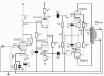
Am I correct in reading_whilst torturing my already sore eyes_the FB resistor as 330R, the frequency correction cap as 3.9nF and the cathode bias resistor as 6.8R?
What's the purpose of the cap the bias resistor is standing on? Never seen it done like this before....
The rest of the diagram looks straightforward enough..it's just input I'm having trouble with.
Cheers,
Hi,
The biasing of that tube is also... odd. Unless I'm reading the value of the feedback resistor wrong, which may be possible because the drawing is pretty fuzzy.
Am I correct in reading_whilst torturing my already sore eyes_the FB resistor as 330R, the frequency correction cap as 3.9nF and the cathode bias resistor as 6.8R?
What's the purpose of the cap the bias resistor is standing on? Never seen it done like this before....
The rest of the diagram looks straightforward enough..it's just input I'm having trouble with.
Cheers,
Re: FUNNIEST KT88 EVER?
Frank,
You are right, that is really odd. With my blurry schematic decoder glasses turned up full I see the cap bypass R is 4700 uF, the 6.8 ohm R in series with it allows some portion of the NFB to act on the tube cathode (developed across this R). Note that the DC cathode current flows in its entirety through the speaker winding of the output xfmer. Very odd circuit! This means that loudspeaker loading and back EMF will effect bias on the input stage. That huge 4700uF cap is there to try to smooth over this back EMF problem I guess. Maybe this amp is prone to motorboating and this was the cure? Play with this cap value and one could have a dynamic processor amplifier all in one!
Now that's also funny!
fdegrove said:Hi,
Am I correct in reading_whilst torturing my already sore eyes_the FB resistor as 330R, the frequency correction cap as 3.9nF and the cathode bias resistor as 6.8R?
What's the purpose of the cap the bias resistor is standing on? Never seen it done like this before....
The rest of the diagram looks straightforward enough..it's just input I'm having trouble with.
Cheers,
Frank,
You are right, that is really odd. With my blurry schematic decoder glasses turned up full I see the cap bypass R is 4700 uF, the 6.8 ohm R in series with it allows some portion of the NFB to act on the tube cathode (developed across this R). Note that the DC cathode current flows in its entirety through the speaker winding of the output xfmer. Very odd circuit! This means that loudspeaker loading and back EMF will effect bias on the input stage. That huge 4700uF cap is there to try to smooth over this back EMF problem I guess. Maybe this amp is prone to motorboating and this was the cure? Play with this cap value and one could have a dynamic processor amplifier all in one!
Now that's also funny!
Thje 4700u cap lets the 6R8 set the feedback and overall gain at AC. It has to be that big because of the small size of the feedback resistor. Part of the "funny" may be my eyes- I thought the screen resistor was 330K not 330R. If the latter, this is a pretty normal triode connection. One can still do better with a higher mu "real" triode like the ones I mentioned. Better still is the 12BZ7, but it's a rarish bird.
One disadvantage to having the cathode current flow through the secondary is the effect on magnetization; that could be cured with a CT secondary. Another is that you'll inevitably get some offset. The back-EMF stuff is normal for any feedback amp.
And finally, I have a prejudice against the 12AU7 used in the diff amp- I've never been able to use this tube without experiencing higher distortion. My own choice for that hole would be a 6SN7. But "check on a song oooh," as the French say.
Hi,
But it's an excellent bird...as is the AZ7, BTW.
Thanks for the explanation...I figured something like that but didn't think it funny, rather errrrrrr...not so smart given the alternatives.
You're not alone on that one...I avoid 12AU7s/ECC82s in a NFB loop like the plague: bright and anemic come immediately to mind, o-scope shows it too.
Either the 6SN7 or if real estate is tight a 6CG7/6FQ7 would cure it for me.
Cheers,
Better still is the 12BZ7, but it's a rarish bird.
But it's an excellent bird...as is the AZ7, BTW.
Thanks for the explanation...I figured something like that but didn't think it funny, rather errrrrrr...not so smart given the alternatives.
I have a prejudice against the 12AU7 used in the diff amp- I've never been able to use this tube without experiencing higher distortion.
You're not alone on that one...I avoid 12AU7s/ECC82s in a NFB loop like the plague: bright and anemic come immediately to mind, o-scope shows it too.
Either the 6SN7 or if real estate is tight a 6CG7/6FQ7 would cure it for me.
Cheers,
'ere, I 'aven't stuck my oar in yet!
You chaps are saying that the feedback is funny, but if it were a transistor amplifier, you'd say it was completely conventional! It's a better method because it degenerates the gain to unity at low frequencies instead of producing a sub-sonic bump.
There really isn't any problem with passing that little bit of DC through the output transformer. Suppose that first stage passed 3mA of cathode current, with a typical output transformer turns ratio of 30:1, that would be equivalent to an imbalance of 100uA in the output valves. Would you be worried about that?
That feedback scheme is far better than the traditional method...
"You CAN, guru, you CAN!"
Whether you get a bump or not ought to (I think) only depend on the relationship between the time constants of the amp itself and the feedback loop, not their topology. At low frequencies, the circuit shown tends toward unity gain. With a conventional (by valve standards!) feedback connection, the gain tends toward... well, the "normal" closed loop gain. When you get peaking, it's because the time constants in the open loop (coupling caps and transformer, mainly) aren't sufficiently separated. That would be the case even more so if I were taking the closed loop gain to unity. In either case, staggering the time constants properly will eliminate any tendency to peak for either connection.
What am I missing?
(note in passing: if you could read those values, you were a much better behaved teen than I was)
Well, the output transformer primary inductance changes rather a lot with level. Juggling the time constants to achieve stability with the traditional feedback scheme generally means making a coupling capacitor rather small. And that means that feedback that should have been mopping up distortion in the output transformer is correcting LF loss in the open-loop amplifier.
Of course, you could juggle the time constants by making that cathode bypass electrolytic really large. But that ensures trouble when you overload the amplifier.
I couldn't read those values either. (The hair on the palms of my hands gets in the way.)
Of course, you could juggle the time constants by making that cathode bypass electrolytic really large. But that ensures trouble when you overload the amplifier.
I couldn't read those values either. (The hair on the palms of my hands gets in the way.)
I'm blind, I tell ya!
Well, let's take an example where the feedback resistor is tied to the top of the cathode bias resistor and hence directly to the cathode. In fact, let's do that with the example circuit. If we go to a 12AX7, we will need roughly a 1K cathode resistor, with a proportionately larger feedback resistor. With 100K on the plate, the first hole should give a gain of roughly 35 (open loop), which is adequate given the gain of the following diff amp. For a plate resistor of 200K, the gain rises to roughly 55. The feedback resistor will be something like 20-40K, very workable values.
So, where would the advantage be in taking the closed loop gain down to unity? Doesn't that challenge the stability of the circuit by increasing the feedback factor if it happens before the open-loop rolloffs? And if it happens at a frequency well below the open loop rolloffs, what good is it doing?
Sorry to be a pest, I just want to wrap my head around this a bit better.
Agreed, taking the closed loop gain to unity means that the feedback factor is greater, and that risks LF instability. But look at the values that were typically used for that cathode capacitor. At smallish signal levels, the primary inductance of the output transformer is high, so the amplifier has gain down to a very low frequency. But the cathode capacitor prevents negative feedback, causing a bump in the LF response, typically at about 1Hz, putting it right into motorboating territory. The result is a frequency response and stability that's dependent on level (output transformer primary inductance).
I think it's a really good idea to try to make everything stay as stable as possible with level. Mind you, I would rather not have that cathode capacitor in the first place. I'd rather use a differential pair for the feedback or just ditch that capacitor. Another interesting possibility is to say "Who cares if the amplifier inverts?" and use shunt feedback.
I think it's a really good idea to try to make everything stay as stable as possible with level. Mind you, I would rather not have that cathode capacitor in the first place. I'd rather use a differential pair for the feedback or just ditch that capacitor. Another interesting possibility is to say "Who cares if the amplifier inverts?" and use shunt feedback.
This his a WAD schema. On this net URL you can see a recent build version based on with an optimised PSU. Sorry but it's in french.
Yeah, that is same thing, and values are easier to read
 . Sorry for that but I have to resize it to put it in here, I think I 've done hell of a job. Still, there is a matter of 6au6, I'm bit confused what I've got to do to replace it
Lurking around, bump into this http://www.ptsoundlab.com/sectubes/schemas/6550/classa40wwad/classa40w6550.htm is it possible to convert this one from ultralinaer into triode mode ( again, what to do?).
Sorry to be 'pain in ...' ,Thanks in advance
To convert to triode, remove the 2k2 screen resistors. Tie the screen of each power tube to its plate using about a 100 ohm 2W resistor.
You may have to diddle the compensation a bit to get the cleanest square waves.
So, what's the theme? Convert all the triodes to UL and all the ULs to triode?
You may have to diddle the compensation a bit to get the cleanest square waves.
So, what's the theme? Convert all the triodes to UL and all the ULs to triode?
Hi,
You could replace it with half of a 12AX7 for instance after adjusting plate load resistor and bias resistor or configure it as a diffamp with the second triode's grid either grounded or as input node for the NFB loop.
ROTFLMAO. I thought school hadn't started yet...
Cheers,
Still, there is a matter of 6au6, I'm bit confused what I've got to do to replace it
You could replace it with half of a 12AX7 for instance after adjusting plate load resistor and bias resistor or configure it as a diffamp with the second triode's grid either grounded or as input node for the NFB loop.
So, what's the theme? Convert all the triodes to UL and all the ULs to triode?
ROTFLMAO. I thought school hadn't started yet...
Cheers,
- Status
- This old topic is closed. If you want to reopen this topic, contact a moderator using the "Report Post" button.
- Home
- Amplifiers
- Tubes / Valves
- KT88 power amp