Hey guys, I'm new to the site- so go easy on me. Anyway, I've recently acquired an old SE 6bq5 amp- and I intend to rebuild it. I will keep only the iron and the chassis. Here's the questions:
1. I would like to add a preamp section and attenuator to this amp- (I have a whole lot of 7au7s laying around; Ideas??)
2. If I were to add a preamp to this guy, could I simply take the B+ from the existing supply (parallel with) and use that for the preamp section??
3. The schematic would have to be simple, cheap and preferably two-tubes, but I tolerate one tube (worried about crosstalk); Any ideas??
4. I have a 100k stepped attenuator sitting around, could we use that??
I could spend time doing trial-and-error to figure-out my own design, but I figured I'd try here first.
Thanks--------------
cadaverdog said:Hey guys, I'm new to the site- so go easy on me. Anyway, I've recently acquired an old SE 6bq5 amp- and I intend to rebuild it. I will keep only the iron and the chassis. Here's the questions:
1. I would like to add a preamp section and attenuator to this amp- (I have a whole lot of 7au7s laying around; Ideas??)
2. If I were to add a preamp to this guy, could I simply take the B+ from the existing supply (parallel with) and use that for the preamp section??
3. The schematic would have to be simple, cheap and preferably two-tubes, but I tolerate one tube (worried about crosstalk); Any ideas??
4. I have a 100k stepped attenuator sitting around, could we use that??
I could spend time doing trial-and-error to figure-out my own design, but I figured I'd try here first.
Thanks--------------
I you are using a CD player as a source you really don't need a preamp per se. Just use the stepped attenuator at the front end of the gain stage. I built a 5687/EL84 SE amp using the power transformer from one of those old amps and it worked great. You should have no problem finding a schematic using google. As for the 7au7s you can use a filtered DC filamentr supply with a 3.3 ohm dropping resistor for a voltage of around 6.5 volts or so. Or you can just use AC filament voltage. The 7au7 heater voltage spec is +/- .7 volts so 6.3 volts will work fine. They are cheap to! Hope that helps.
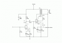
Right now, the complement is one 6bq5 per channel and one 5u4g in the PS. The input is ran directly into the grids with no cap whatsoever, just a pair of paralleled resistors (one to ground and one for the signal to pass through. I mean, if you think that maybe I don't need a preamp section, I won't use one; it's probably silly to add more circuitry to an already line-level source anyway. BTW, this leads me into a couple of other questions:
1. If I add the attenuator, do I remove those resistors?
2. I was wondering why there was no sort of DC blocking cap. The only cap in the driver stage is a .0022uf coupling the cathode to the anode- (the cathode is being fed-back from the positive line from the secondary of the OPT.)
Thanks for the reply!!
I see. I was assuming that it had a 12AX7 gain stage as most of those types of amps do. The question is will the 6.3 volt winding handle another tube filament or did they spec the tolerances too tight. Measure the DC resistance of the 6.3 volt winding (with the power off) after isolating it. Divide 6.3 by the DC resistance value and the dividend will give you a rough idea as to how much current the 6.3 volt winding can handle. I'm not sure that I would use a 7au7 as a gain tube in an EL84 amp. A 6922 or a 5687/e182cc would be my choices. That is only my opinion though. Different strokes.
Well, I did what you told me and measured the dc resistance of the filament winding......it came out to be around 200milliohms; That would make the current capability of the transformer around 30 amps!! Before you say "that's impossible" I must tell you that this amp looks as if it were only one chassis among two or three- and the transformer was meant to power not only the amp, but also a tuner and preamp section. In fact, there is a "pilot-out" on the chassis that the filament wires from the transformer were at one time connected to. As far as selection with the preamp tubes, I have a good quantity of the following:
6sn7,8sn7,12sn7,7au7,12au7,7247,7025,12ax7wa,5663(button type), and 12bh7a
If any of these will work, let me know.
Thanks again!!
6sn7,8sn7,12sn7,7au7,12au7,7247,7025,12ax7wa,5663(button type), and 12bh7a
If any of these will work, let me know.
Thanks again!!
cadaverdog said:Well, I did what you told me and measured the dc resistance of the filament winding......it came out to be around 200milliohms; That would make the current capability of the transformer around 30 amps!! Before you say "that's impossible" I must tell you that this amp looks as if it were only one chassis among two or three- and the transformer was meant to power not only the amp, but also a tuner and preamp section. In fact, there is a "pilot-out" on the chassis that the filament wires from the transformer were at one time connected to. As far as selection with the preamp tubes, I have a good quantity of the following:
6sn7,8sn7,12sn7,7au7,12au7,7247,7025,12ax7wa,5663(button type), and 12bh7a
If any of these will work, let me know.
Thanks again!!
Go with the 12BH7 by all means. A nice tube. You also might have to put a couple of dropping resistors in the filament supply to bring the voltage into spec for supplying just three tubes. I will post back some ideas about operating points later today. 30 amps? Did you isolate the winding?
I'm not sure what you meant by " isolating the windings ", but I simply measured the resistance between the two leads (the heater winding) with my dmm. The transfomer has been totally disconnected from the circuit. 12bh7 huh, I've never even thought of using those tubes............. Let me know if you know of a circuit that might work. I will even consider a totally different circuit if I could still use the chassis, the 5u4 (gotta be tube rectified), the 5k opt's, my expensive 100k attenuator, and the power transformer. BTW when I first got this thing home and powered it up, the transformer seemed like a total overkill being that the plates were glowing red and the anodes were reading 420v!! I proceeded to check the rest of the caps, resistors, and connections (there's only like 15 parts in the whole amp)- and everything was fine. No burnt resistors, shorted or open caps, bad rectifier tube, etc.
Thanks!!
Thanks!!
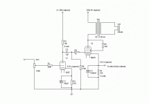
I prefer the 5687 to any of the 9 pin tubes you mentioned. The 12BH7 is supposed to be a fine sounding tube also. I have a schematic for a 5687/ EL84 SE amp that was my first project. I will send it to you if you would like. You will need to take some measurements of the power transformer and design a power supply but I can help with that. Also your filament winding voltage may end up too high but a couple of well placed resistors can take care of that also. I'll post the schematic when I get home from work.
G
G
Couple things:
First of all, this schematic appeals to my minimalist philosophy and I'm loving the way this looks (what's the power output?). Yes, I would like to see your PS ideas for this guy; (I definately want to use the 5u4 though.) I don't like chokes, nor do I have room for one an the chassis- so that may or may not be a problem. I'm also thinking about filament regulation with an lm350. BTW, would I add the attenuator before the 100k?? I'm assuming that the screen grid (labeled "to B+") is wired directly to 250 volts. Lastly, the OPT's are definately rated @ 5k with 8 and 4 ohm taps, not 4.8k like the schematic details.
Thanks!!
Hi cadaverdog
If you want to experiment other kind of circuits - with other voltage amplifing tube - you may give the 12AX7 or 7025 (can be used instead of 12AX7wa, having even better specs) a try. There are lots of schematics available for this combination of tubes. You can even search for schematics using the ECL86, which is a EL84 and half a 12AX7.
Erik
cadaverdog said:Couple things:
First of all, this schematic appeals to my minimalist philosophy and I'm loving the way this looks (what's the power output?). Yes, I would like to see your PS ideas for this guy; (I definately want to use the 5u4 though.) I don't like chokes, nor do I have room for one an the chassis- so that may or may not be a problem. I'm also thinking about filament regulation with an lm350. BTW, would I add the attenuator before the 100k?? I'm assuming that the screen grid (labeled "to B+") is wired directly to 250 volts. Lastly, the OPT's are definately rated @ 5k with 8 and 4 ohm taps, not 4.8k like the schematic details.
Thanks!!
Basically the schematic is a Decware Zen using a 5687 in the gain stage instead of a 6N1P. The output power is about 3 watts. I didn't use a choke in the power supply of this amp so that won't be a problem. The attenuator would take the place of the 100K resistor. I had no problems with hum but if you want to go DC on the filaments I would start out with just a filtered DC supply. Keep the first project simple. Basically I need for you to measure the no load voltage on your power transformer from one lead to the center tap and then measure the winding resistance from one lead to the center tap and I can tweak the power supply to fit your transformer. The layout of the amp I built can be found here:
https://athena.safe-order.net/decware/zkit02.htm
Some of the values are different but that is essentially the amp I built.
After downloading the schematic from Decware, I would have to say that this is definately the way to go. Everything I want is there and I could put all of it on my chassis with little or no modification. I did some measurements on my PT and came up with the following:
Filament 1: 7.25V .2 ohms
Filament 2: 5.65V .3 ohms
High Volt : 366V-0-366V 63.5 ohms (R-from one lead to CT)
There are no center-taps on the filaments, and judging by the Decware schematic- that might be a problem. Also, the 01uf coupling cap seems a little small (add a 1uf?) What do you think?
Filament 1: 7.25V .2 ohms
Filament 2: 5.65V .3 ohms
High Volt : 366V-0-366V 63.5 ohms (R-from one lead to CT)
There are no center-taps on the filaments, and judging by the Decware schematic- that might be a problem. Also, the 01uf coupling cap seems a little small (add a 1uf?) What do you think?
cadaverdog said:After downloading the schematic from Decware, I would have to say that this is definately the way to go. Everything I want is there and I could put all of it on my chassis with little or no modification. I did some measurements on my PT and came up with the following:
Filament 1: 7.25V .2 ohms
Filament 2: 5.65V .3 ohms
High Volt : 366V-0-366V 63.5 ohms (R-from one lead to CT)
There are no center-taps on the filaments, and judging by the Decware schematic- that might be a problem. Also, the 01uf coupling cap seems a little small (add a 1uf?) What do you think?
Well you can see the finished product for yourself below. No CT on the filament winding is not a problem. Especially if you are going to be using a regulated DC supply for the filaments. Yes the .1 cap is too small. Use a 1uF 600v cap. I will post the PSU in a few minutes.
Attachments
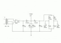
Here is the PSU. Keep in mind that the first resistor (R1) is dropping a lot of voltage. Make sure to use a 25 watt wirewound resistor. Michael Percy Audio is a good place for the 25 watt ww and for Mill's 12 and 5 watt wirewounds. That is pretty much all I use in power supplies for power amps. He also sells Kiwame carbon film resistors that work very well in tube amps as plate and cathode resistors. The choice is yours.
Attachments
Hi,
1µF into 470K?
0.220µF would already be much more low frequency than the OPT can pass.
Don't get me wrong, it will of course work but the higher the RC constant the slower the cap will be.
This could be something worth fiddling a little with. You may find the amp's transient improve with smaller value coupling caps, moreover I'd doubt you'd notice any difference in the bass response.
Cheers,
Damn. The .047 coupling cap should read 1uF. Later.
1µF into 470K?
0.220µF would already be much more low frequency than the OPT can pass.
Don't get me wrong, it will of course work but the higher the RC constant the slower the cap will be.
This could be something worth fiddling a little with. You may find the amp's transient improve with smaller value coupling caps, moreover I'd doubt you'd notice any difference in the bass response.
Cheers,
fdegrove said:Hi,
Any particular reason why the cathode resistors of the 6BQ5s are shared between channels?
Cheers,
Hi Frank,
No. Other than when I was building this amp the schematic model I used biased the output tubes this way. I have since built a different amp and used separate cathode resistors. You are correct in pointing that out. Separate resistors would probably be preferable. If you do use separate cathode resistors CadaverDog you should double the value to 300 ohms for each resistor as yo will only have half of the current flowing through the resistor and therefore only half of the desired voltage drop (10.5v - 11v).
- Status
- This old topic is closed. If you want to reopen this topic, contact a moderator using the "Report Post" button.
- Home
- Amplifiers
- Tubes / Valves
- Need advice on old 6bq5 amp...........


