Hi guys,
I'm stuck in this. I have tried to contact mr. Pimm to ask him directly but I suspect that he has no time or that he thought that I am spaming him.....
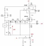
I am trying to calculate values for the G. Pimm's CCS Rev. 3 with E180F and 27 tubes. Plate current should be 5mA. Plate voltage on 27 should be 163V. Cathode of 27 to ground is 11V. HT voltage should be 394V so I should have approx 205V on the penthode. Ug2 for the E180F should be 326V (from ground to screen grid ¡V or approx. 138V from the cathode of the penthode), Ig2= 2,4mA. Ug1=-1.8V measured from the cathode of the E180F.
I have calculated the values for the R1, R3, R4 as from mr. Pimm's home page.
Please look at it and tell me if the values are correct.........
R1=21V/5mA=4k2 / 5W
R3= (395-163-24,5-1,8-138)/ (2,39mA+1,27mA)=18k4 aprox.
R4=(138V-40V)/1,27mA=77k aprox.
Attached is the schematic from which I have spoken and the schematic that should be eventually corrected.
Please correct every value if needed (also the working points for the penthode- I have low experience working with penthodes ƒ¼).
Thanks in advance and best regards
daniel
I'm stuck in this. I have tried to contact mr. Pimm to ask him directly but I suspect that he has no time or that he thought that I am spaming him.....
I am trying to calculate values for the G. Pimm's CCS Rev. 3 with E180F and 27 tubes. Plate current should be 5mA. Plate voltage on 27 should be 163V. Cathode of 27 to ground is 11V. HT voltage should be 394V so I should have approx 205V on the penthode. Ug2 for the E180F should be 326V (from ground to screen grid ¡V or approx. 138V from the cathode of the penthode), Ig2= 2,4mA. Ug1=-1.8V measured from the cathode of the E180F.
I have calculated the values for the R1, R3, R4 as from mr. Pimm's home page.
Please look at it and tell me if the values are correct.........
R1=21V/5mA=4k2 / 5W
R3= (395-163-24,5-1,8-138)/ (2,39mA+1,27mA)=18k4 aprox.
R4=(138V-40V)/1,27mA=77k aprox.
Attached is the schematic from which I have spoken and the schematic that should be eventually corrected.
Please correct every value if needed (also the working points for the penthode- I have low experience working with penthodes ƒ¼).
Thanks in advance and best regards
daniel
Attachments
Hi Daniel,
I've just not had time or the mental capacity to answer e-mails for a couple of weeks. The place I work is in the middle of moving a large part of the operation from one building to another. The planning followed by execution has been very consuming. Things are starting to settle down now so I can get back to having fun.
Your numbers look good to me. The only thing that looks out is the current shown for the CCS diode, 1.27ma. If you are using a CCS diode that passes 1.27ma then all is well with one caviot. The ratio of current through the reference to the total current is pretty high at 2.39ma/1.27ma. The specified part passes .75ma. This would facilitate increasing the value of R3 some to compensate.
I suspect that the reason that the newer version CCS's using the cascade connected LND150's sound better is because the reference current is lower, running around .35ma. Also, with the LND150's feeding a heavly filtered RC network using the mu output as the summing node, any noise from from the LND150's is coupled into the low impedance of the summing node making for a very quiet voltage reference.
To verify that things are working as expected check the grid bias of the pentode. Should be in the range of -1 to -3 volts. Decreasing the value of R3 will increase the grid bias. Also check the voltage across the CCS diode and adjust R4 if nessasary.
Hope this helps
Gary
Dear mr. Gary,
Thanks for the post......... I would like to use 0.75mA ccs in that calculation (1N5294)- what is the problem with this calculations is that I can't get out of them (since I didn't do much with penthode's). That was the reason for posting this thread.
Please correct me since I would like to learn how to calculate those ccs's so I could use them whenever I need to use mu follower based circuit's.
For Rev. 3... E180F / 27
R1=20.5V to 32V /5mA= 4k1 to 6k4 say 21V/5mA=4k2/5W
I choose to use B+=395V; Vpl=163.3V (of the triode); Vref=(4k2+5mA)+3,5V=24,5V; Vb=-1.8V; Ug2=Vs==138V;
Ib is the problem- ccs diode says 0,75mA but if I look at Your schematic attached above I can see that R4=33k and voltage dropout across R4 is 112V-70V=42V - that means that the current flowing through R4 in that case =42V/33k=1,27mA. So should I use 1,27mA or 0,75mA and why.
Is=Ig2=2,39mA
So, lets say I use 1,27mA (only for the purpose of correcting the mistakes if there are any- I supose that You have used 0.75mA in that position- so please correct me);
R4=(395-163,3-24,5-1,8-138)/(2,39mA+1,27mA)=67,4V/3,66mA=18k4 aprox.
and also 1,27mA change the calculated value for the R4 that seems to become R4=(138-40)/1,27mA=77k approx.
So the main question is how much current is flowing through the R4 (0,75mA like it should - or little bit more because of the nonlinearity of the zenner diode- but that is not that much - to reach 1,27mA).
I would like to calculate everything before turning it on- I love those tube to much to burn them
Also, I would like to ask You- did You try classic mu- follower and how did it sound with 27 triode- I think that the triode is working easier so it should work better? Supplier for the LD150 and 1N5294 is Mouser- right? Any substitutions for them?
Thanks for help
Very best regards and hope this won't take to much of Your time (I know how that is when You don't have to much time- then You take it from the time for sleeping and then Your boss is not very happy when You look like in the morning)
daniel
Thanks for the post......... I would like to use 0.75mA ccs in that calculation (1N5294)- what is the problem with this calculations is that I can't get out of them (since I didn't do much with penthode's). That was the reason for posting this thread.
Please correct me since I would like to learn how to calculate those ccs's so I could use them whenever I need to use mu follower based circuit's.
For Rev. 3... E180F / 27
R1=20.5V to 32V /5mA= 4k1 to 6k4 say 21V/5mA=4k2/5W
I choose to use B+=395V; Vpl=163.3V (of the triode); Vref=(4k2+5mA)+3,5V=24,5V; Vb=-1.8V; Ug2=Vs==138V;
Ib is the problem- ccs diode says 0,75mA but if I look at Your schematic attached above I can see that R4=33k and voltage dropout across R4 is 112V-70V=42V - that means that the current flowing through R4 in that case =42V/33k=1,27mA. So should I use 1,27mA or 0,75mA and why.
Is=Ig2=2,39mA
So, lets say I use 1,27mA (only for the purpose of correcting the mistakes if there are any- I supose that You have used 0.75mA in that position- so please correct me);
R4=(395-163,3-24,5-1,8-138)/(2,39mA+1,27mA)=67,4V/3,66mA=18k4 aprox.
and also 1,27mA change the calculated value for the R4 that seems to become R4=(138-40)/1,27mA=77k approx.
So the main question is how much current is flowing through the R4 (0,75mA like it should - or little bit more because of the nonlinearity of the zenner diode- but that is not that much - to reach 1,27mA).
I would like to calculate everything before turning it on- I love those tube to much to burn them
Also, I would like to ask You- did You try classic mu- follower and how did it sound with 27 triode- I think that the triode is working easier so it should work better? Supplier for the LD150 and 1N5294 is Mouser- right? Any substitutions for them?
Thanks for help
Very best regards and hope this won't take to much of Your time (I know how that is when You don't have to much time- then You take it from the time for sleeping and then Your boss is not very happy when You look like
in the morning) daniel
Hi,
Consider IR’s photo voltaic isolators for biasing the fet. The PVI1050 can generate 10-12V and has a very low 1 pf input-output capacitance. No hassle with current sources then.
I am fiddling with cascoded fets in a Mu stage and will try this soon (when I find some time).
Cheers
Consider IR’s photo voltaic isolators for biasing the fet. The PVI1050 can generate 10-12V and has a very low 1 pf input-output capacitance. No hassle with current sources then.
I am fiddling with cascoded fets in a Mu stage and will try this soon (when I find some time).
Cheers
Attachments

Hi Daniel,
Did not try the classical one with a penthode cascode. Only expemented with mos-fet cascodes. But the loading of the next stage or cable (capacitance/resistance) affects the sound as well to my experience. Also loading the source of the fet with an extra 5 mA current sink made the sound more neutral. It raises the Gm of the fet. But if a more neutral sound is better is a matter of taste IMHO.
Cheers
Hi Daniel,
I'm a little bit confused here.
What is confusing me is I don't know where you are getting the 33K value for R4 from. The schematic refered to above does not show a value for R4. If the voltage drop shown is calculated against the .75ma current it would be 56K.
No current flows through the zener diode when things are setup correctly, the zener is there to protect the CCS diode during startup and shutdown.
I have not tried using a classic mu follower so can't comment.
The LND150 and 1N5294 are sourced from Mouser. As far as I know there is not a substitution for the LND150. There are other CCS diodes available but most of them are only good for 50 volts.
Gary
I'm a little bit confused here.
I choose to use B+=395V; Vpl=163.3V (of the triode); Vref=(4k2+5mA)+3,5V=24,5V; Vb=-1.8V; Ug2=Vs==138V;
Ib is the problem- ccs diode says 0,75mA but if I look at Your schematic attached above I can see that R4=33k and voltage dropout across R4 is 112V-70V=42V - that means that the current flowing through R4 in that case =42V/33k=1,27mA. So should I use 1,27mA or 0,75mA and why.
Is=Ig2=2,39mA
What is confusing me is I don't know where you are getting the 33K value for R4 from. The schematic refered to above does not show a value for R4. If the voltage drop shown is calculated against the .75ma current it would be 56K.
No current flows through the zener diode when things are setup correctly, the zener is there to protect the CCS diode during startup and shutdown.
Also, I would like to ask You- did You try classic mu- follower and how did it sound with 27 triode- I think that the triode is working easier so it should work better? Supplier for the LD150 and 1N5294 is Mouser- right? Any substitutions for them?
I have not tried using a classic mu follower so can't comment.
The LND150 and 1N5294 are sourced from Mouser. As far as I know there is not a substitution for the LND150. There are other CCS diodes available but most of them are only good for 50 volts.
Gary
I am on a vacation so don't be angry if I don't reply emediatelly. Under the R11 is a blue box with blue letters in that schematic. In there You have said that You have used 27/6AU6 combination and in respect of that Your chosen value for the R4 is 33k. Other values are in there also. That values is what I was looking......and trying to figure the calculation....
Best regards
daniel
p.s. after the 20. of august I'm back so I will reply sooner.
best regards

Best regards
daniel
p.s. after the 20. of august I'm back so I will reply sooner.
best regards
Hi!
Mr. Pimm or anyone who is willing to reply- on a first post of this thread I have attached one schematic. Here it is attached again (I have circled what I was looking at when I take my calculations).
"Voltages are measured with respect to CCS output. The measurements are from my 27 line stage using 6au6's and set for 5ma. R1 is 5.5k, R3 is 22k and R4 is 33k. Voltage across ccs is 150V."
All my calculations were from that point and values of the components. I was trying to figure the way it works and how to calculate it so I could use it for my diy line stage also with 27 and probably for my power amplifier with 211 output triode and 5687 as a driver.
Thanks to anyone who had nerves to read through down here and takes time to reply.
best regards
daniel
Attachments
- Status
- This old topic is closed. If you want to reopen this topic, contact a moderator using the "Report Post" button.
- Home
- Amplifiers
- Tubes / Valves
- mr. pimm's ccs rev.3?