Hi,
Can I cheat using 1 transformer or will I have to buy another one for a negative bias supply?
http://www.geocities.com/super_bq/Misc/PS_Example_1.JPG
BQ
PS: please click on http://www.geocities.com/super_bq/Misc/
and click on PS_Example_1.JPG as Geocities doesn't allow direct linking.
Can I cheat using 1 transformer or will I have to buy another one for a negative bias supply?
An externally hosted image should be here but it was not working when we last tested it.
http://www.geocities.com/super_bq/Misc/PS_Example_1.JPG
BQ
PS: please click on http://www.geocities.com/super_bq/Misc/
and click on PS_Example_1.JPG as Geocities doesn't allow direct linking.
"Y'know, funny looking. Yah, sure."
In any case, you can get by with a single transformer (assuming it's got the right voltages), but not the way you're drawn it. You want to ground the transformer CT, which is the common between the positive and negative rails' return leads (ie, the negative lead of the positive supply and the positive lead of the negative supply). The feed the positive rail filter with the + output from the bridge and the negative rail filter with the - output of the bridge. Your output voltage will be on the order of +/-1.4 times the voltage on either side of the CT. IOW, for a 400VCT secondary (200-0-200), your outputs will be on the order of +280 and -280.
In any case, you can get by with a single transformer (assuming it's got the right voltages), but not the way you're drawn it. You want to ground the transformer CT, which is the common between the positive and negative rails' return leads (ie, the negative lead of the positive supply and the positive lead of the negative supply). The feed the positive rail filter with the + output from the bridge and the negative rail filter with the - output of the bridge. Your output voltage will be on the order of +/-1.4 times the voltage on either side of the CT. IOW, for a 400VCT secondary (200-0-200), your outputs will be on the order of +280 and -280.
But require different output voltages
SY,
I understand Dual Complementary FW rectification. Thanks for your example. However, I wanted to know if it's possible to have 2 different supply voltages off the single secondary?
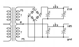
With a 75-0-75 transformers. I would like 212VDC (done by single bridge full wave). As you can see in the drawing, I also want a 106VDC supply (which taken off the 75 vac & CT lead to GND).
I've never seen it done this way and wonder if it presents too much loading on the single 2ndary winding of the transformer?
BQ
SY,
I understand Dual Complementary FW rectification. Thanks for your example. However, I wanted to know if it's possible to have 2 different supply voltages off the single secondary?
With a 75-0-75 transformers. I would like 212VDC (done by single bridge full wave). As you can see in the drawing, I also want a 106VDC supply (which taken off the 75 vac & CT lead to GND).
I've never seen it done this way and wonder if it presents too much loading on the single 2ndary winding of the transformer?
BQ
BQ,
Consider Pete Millett's scheme for 2 rails from 1 CT winding. Wire a FW bridge to the ends of the CT 150 VAC winding, that gives you your high rail. Connect an additional diode's anode to the CT. You take the low rail from the additional diode's cathode. Both rails are full wave rectified. The grounded pair of diodes in the bridge serves both rails.
You should be fine as long as you don't exceed the capability of the power trafo secondary. With cap. I/P filters, you can access only 1/2 of the secondary's VA rating.
- Status
- This old topic is closed. If you want to reopen this topic, contact a moderator using the "Report Post" button.
- Home
- Amplifiers
- Tubes / Valves
- Dual rectification off single sencondary transformer question