fdegrove said:Hi,
Guido,
Regarding the preference (subjective thing, I know) , when the + side of the heater is grounded won't that change the bias with the respective heater voltage amount?
I mean, +5V side grounded means -5V added to negative bias or do I see this the wrong way?
If I am correct that may well account for the audible difference I suppose...
Cheers,")
Hi Frank
Yes, the bias changes when reversing polarity. In the listening tests we corrected for this change. After all, the effective (negative) grid voltage had to be changed, which may change the ease of drive. I assume this effect is of minor importanve though.
I still think it is in the current distribution of the tubes, which is never symmetrical.
best regards
Hi,
Guido,
Ah...I wasn't sure you had compensated for that.
Exactly.
Current distribution may well vary from tube to tube though as I can't imagine a factory worker being able to tell the direction .
So some experimenting may be called for before deciding how hooking it up, I suppose.
Thanx.
Cheers,
Guido,
In the listening tests we corrected for this change
Ah...I wasn't sure you had compensated for that.
I still think it is in the current distribution of the tubes, which is never symmetrical.
Exactly.
Current distribution may well vary from tube to tube though as I can't imagine a factory worker being able to tell the direction .
So some experimenting may be called for before deciding how hooking it up, I suppose.
Thanx.
Cheers,
Guido Tent said:Yes, the bias changes when reversing polarity. In the listening tests we corrected for this change. After all, the effective (negative) grid voltage had to be changed, which may change the ease of drive. I assume this effect is of minor importanve though.
But the anode-cathode voltage also changes by 5V given a constant B+. This will change the load line. Did you compensate for that too?
Anyway the AC audio current has to flow through the DC gradient across the filament when the filament is only grounded at one side. But it is still AC. Whether you ground the + or – side of the filament, that gradient stays the same.
It is known that with lo mu tubes (with wide grid spacing) magnetic fields influences also electron flow...? In this case the magnetic field generated by the filament current?
Up till now, just some observations but no explanation. Think it will be hard to find some explanation, although it stays intriguing
Cheers
hi Guido
Thanks!
I agree! The resistors on the cathode are the self-bias resistors, using different values according to Thorsten advice to balance the currents flowing from either end of the filament -
http://db.audioasylum.com/cgi/m.mpl?forum=set&n=31256&session=
The 100uF Cerafine is the cathode bypass capacitor.
No need to balance the +/-.
On the positive side (T1 - Q1) Is only a ripple smoother - it drops about 2V or so and rejects noise. It's more like a voltage source (at dc) than a current source.
On the negative side T2 - T3 is the current source which is adjusted to make the right voltage appear across the filament.
The interesting thing about the Sovtek is the big difference between ac and current source heating. It's so noisy and bad sounding on ac - but sounds wonderful using the circuit in post #35.
The construction of the old Sovtek 300B uses a very thin filament, which at least partly accounts for the bad sound and microphony
If you're using Sovtek or another cheap DHT with ac heating, you owe it to yourself to try current-driven heat! Get Guido's heater supply, or, if you're transistor-competent, build your own design! It's much cheaper than upgrading to fancy 300Bs and probably just as good.
Guido Tent said:
Hi
This is an impressive setup
Thanks!
Personally I am in favour of high impedance across the filaments, but as you can see, many ways lead to rome....(they are all long though
I agree! The resistors on the cathode are the self-bias resistors, using different values according to Thorsten advice to balance the currents flowing from either end of the filament -
http://db.audioasylum.com/cgi/m.mpl?forum=set&n=31256&session=
The 100uF Cerafine is the cathode bypass capacitor.
I guess balancing the sources is tricky, not ?
No need to balance the +/-.
On the positive side (T1 - Q1) Is only a ripple smoother - it drops about 2V or so and rejects noise. It's more like a voltage source (at dc) than a current source.
On the negative side T2 - T3 is the current source which is adjusted to make the right voltage appear across the filament.
Oh, one last word, the Sovtek is not the best sounding tube, to be honest I iuse these for first time testing only......
The interesting thing about the Sovtek is the big difference between ac and current source heating. It's so noisy and bad sounding on ac - but sounds wonderful using the circuit in post #35.
The construction of the old Sovtek 300B uses a very thin filament, which at least partly accounts for the bad sound and microphony
If you're using Sovtek or another cheap DHT with ac heating, you owe it to yourself to try current-driven heat! Get Guido's heater supply, or, if you're transistor-competent, build your own design! It's much cheaper than upgrading to fancy 300Bs and probably just as good.
Rod Coleman said:
I agree! The resistors on the cathode are the self-bias resistors, using different values according to Thorsten advice to balance the currents flowing from either end of the filament -
http://db.audioasylum.com/cgi/m.mpl?forum=set&n=31256&session=
The 100uF Cerafine is the cathode bypass capacitor.
No need to balance the +/-.
On the positive side (T1 - Q1) Is only a ripple smoother - it drops about 2V or so and rejects noise. It's more like a voltage source (at dc) than a current source.
On the negative side T2 - T3 is the current source which is adjusted to make the right voltage appear across the filament.
The interesting thing about the Sovtek is the big difference between ac and current source heating. It's so noisy and bad sounding on ac - but sounds wonderful using the circuit in post #35.
The construction of the old Sovtek 300B uses a very thin filament, which at least partly accounts for the bad sound and microphony
If you're using Sovtek or another cheap DHT with ac heating, you owe it to yourself to try current-driven heat! Get Guido's heater supply, or, if you're transistor-competent, build your own design! It's much cheaper than upgrading to fancy 300Bs and probably just as good.
Hello Rod,
Yes, the balancing of DC current distribution (density) due to different values in the cathode is a nice one.
Still, the AC distribution can be defined by adding external cap(s) to ground.
On the current source: One follows the other, correct ?
I'll pay more attention to the Sovteks - thanks !
best regards
-
Guido
How about another circuit idea for Push-Pull DHT amps like the Lynn Olson AMITY etc. (Idea ONLY so far - I don't have an AMITY yet, sadly):
Most of the circuit shown in post #35 of this thread can be kept as-is, but with the two push pull valves each having their own return circuit (current sink). That way the two valves can have different voltages (to cover production tolerances):
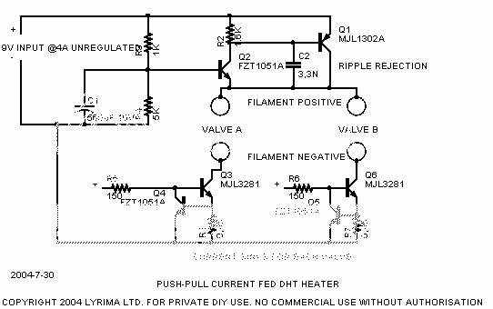
2 x 2A filaments, like the KR300BXLS can be accommodated easily with this circuit. If the transistors are MJL1302A (PNP) and MJL3281 (NPN) - AND mounted on heatsinks of 2~4 deg C/W you can even have shorted filament protection! What's more you can have one filament shorted and the other will carry on working normally, avoiding the risk of cathode stripping in the good valve. Just be aware this means ONLY that the filament is shorted; I don't mean you can short the positive side to the raw supply return. Bypassing the current sink part of the circuit will vanish the safety feature. But if you properly insulate the return node you should be protected against all reasonably likely faults.
Be sure you can cope with the stability test and thermal ratings design/test as noted in post #35 if you attempt to build this circuit; you could burn up your DHTs if you don't check & burn in thoroughly.
Most of the circuit shown in post #35 of this thread can be kept as-is, but with the two push pull valves each having their own return circuit (current sink). That way the two valves can have different voltages (to cover production tolerances):
2 x 2A filaments, like the KR300BXLS can be accommodated easily with this circuit. If the transistors are MJL1302A (PNP) and MJL3281 (NPN) - AND mounted on heatsinks of 2~4 deg C/W you can even have shorted filament protection! What's more you can have one filament shorted and the other will carry on working normally, avoiding the risk of cathode stripping in the good valve. Just be aware this means ONLY that the filament is shorted; I don't mean you can short the positive side to the raw supply return. Bypassing the current sink part of the circuit will vanish the safety feature. But if you properly insulate the return node you should be protected against all reasonably likely faults.
Be sure you can cope with the stability test and thermal ratings design/test as noted in post #35 if you attempt to build this circuit; you could burn up your DHTs if you don't check & burn in thoroughly.
Konnichiwa,
This one has been among the dead for a while, time to voodoo it back among the living.
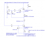
Over the recent times I have been thinking to and fro how one might achieve similar effects to Guido's circuit, preferably short circuit protected, simple and with as few parts and 3-legged fuses as possible. The following Circuit is what I came up with, it SHOULD work (P-Spice says it does) but I have not specifically build it (yet), so beware....
The idea is to make a Circuit that is a high impedance at AC. We already know the "simple" LM1085 Curret Source seems to work fine sonically, but when supplying normal DHT's you need to re-adjust it as valves age and when you change Valves, far from ideal.
In my circuit the 1mH Choke (around 0.5R DCR) together with the 1,000uF Capacitor in effect establishes an AC Current Source where the transconductance of the 3-Pin Regulator in effect amplifies the impedance of the 1mH Choke. The 1,000uF Capacitor together with the 1K resistor between adj and out froms a highpass at 0.16Hz so at DC the whole thing will slowly turn bacvk to a low DCR resistance source.
In order to set the Output voltage accuratly a LM/TL431 is used, here the output voltage would be 5V. In order to stop the LM431 from "regulating away" our nice high output impedance the lower part of the voltage divider which stes the output voltage is bypassed (1st Order LPF at 0.03Hz), thus making sure that audio frequencies the impedance remains high. In the audio range the impedance is limited by the 10K unbypassed resistor in the voltage sensecircuit.
Added to this is a simple common mode filter and Schottky Rectifier Bridge, basically "best practice" for DHT Heater DC Supplies, lest you like to use Thyratron or high current mercury vapour rectifiers like this dude here:
300B SE Amp with 101D Driver, 300B Rectifier and 314A rectified heater supplies....
As usual comments etc welcome.
Sayonara
This one has been among the dead for a while, time to voodoo it back among the living.
Over the recent times I have been thinking to and fro how one might achieve similar effects to Guido's circuit, preferably short circuit protected, simple and with as few parts and 3-legged fuses as possible. The following Circuit is what I came up with, it SHOULD work (P-Spice says it does) but I have not specifically build it (yet), so beware....
An externally hosted image should be here but it was not working when we last tested it.
The idea is to make a Circuit that is a high impedance at AC. We already know the "simple" LM1085 Curret Source seems to work fine sonically, but when supplying normal DHT's you need to re-adjust it as valves age and when you change Valves, far from ideal.
In my circuit the 1mH Choke (around 0.5R DCR) together with the 1,000uF Capacitor in effect establishes an AC Current Source where the transconductance of the 3-Pin Regulator in effect amplifies the impedance of the 1mH Choke. The 1,000uF Capacitor together with the 1K resistor between adj and out froms a highpass at 0.16Hz so at DC the whole thing will slowly turn bacvk to a low DCR resistance source.
In order to set the Output voltage accuratly a LM/TL431 is used, here the output voltage would be 5V. In order to stop the LM431 from "regulating away" our nice high output impedance the lower part of the voltage divider which stes the output voltage is bypassed (1st Order LPF at 0.03Hz), thus making sure that audio frequencies the impedance remains high. In the audio range the impedance is limited by the 10K unbypassed resistor in the voltage sensecircuit.
Added to this is a simple common mode filter and Schottky Rectifier Bridge, basically "best practice" for DHT Heater DC Supplies, lest you like to use Thyratron or high current mercury vapour rectifiers like this dude here:
300B SE Amp with 101D Driver, 300B Rectifier and 314A rectified heater supplies....
As usual comments etc welcome.
Sayonara
Wang san, sumimasen!
Sure its worth raising this one again, its a dinner-money upgrade with far more impact than a mortgage-busting pile of boutique glassware, dielectricware or even old fashioned ironware!
I accept that you're going to have some adjusting to do when you only have a current loop controlling heater power. I did think about adding a voltage loop - with multiple-pole cutoff <1Hz - but decided I don't need it. The heater voltage with the gyrator/transistor current source shown above is plenty stable enough (over the few hundred hours I've run it), and can easily be made adjustable with a low power 20 ohm fixed in series with a 100 ohm/10T trimmer (all across the sense resistor).
I found it worthwhile to spend time finetuning the circuits in both heater terminals - I would certainly recommend testing your circuit with an effective ac break between the rectifier -ve and -F. In that position I like a PNP darlington gyrator formed with FZT1151A (Zetex, superbeta) and a PNP power transistor (smallest you can get which satisfies your safety margin). The specified Cob of the PNPs is what counts (35pF = good; >130pF = bad). The reason for the obsession is (as you know) the -ve current pulses that form the rectifier noise - with plenty of energy >100MHz.
General observation: With 3-terminal regs the multiple internal circuit paths from IN (& ADJ) to OUT risk degrading the insertion loss as frequency gets really high. So, in your circuit, watch out for the ac path from +F through the 1000uF into ADJ!
clic the pic - Easy to build circuit on plain copperclad board (hacksawed pattern) with SMD parts - (2512 cathode resistors, FZT1051A/2SD2061 gyrator, FZT1051A/2SC5511 current source with R47 R56 shunted sense resistors, SANYO 560/10 SVP (20mOhm ESR) caps.....
Thanks to ImageShack for Free Image Hosting
Sure its worth raising this one again, its a dinner-money upgrade with far more impact than a mortgage-busting pile of boutique glassware, dielectricware or even old fashioned ironware!
I accept that you're going to have some adjusting to do when you only have a current loop controlling heater power. I did think about adding a voltage loop - with multiple-pole cutoff <1Hz - but decided I don't need it. The heater voltage with the gyrator/transistor current source shown above is plenty stable enough (over the few hundred hours I've run it), and can easily be made adjustable with a low power 20 ohm fixed in series with a 100 ohm/10T trimmer (all across the sense resistor).
I found it worthwhile to spend time finetuning the circuits in both heater terminals - I would certainly recommend testing your circuit with an effective ac break between the rectifier -ve and -F. In that position I like a PNP darlington gyrator formed with FZT1151A (Zetex, superbeta) and a PNP power transistor (smallest you can get which satisfies your safety margin). The specified Cob of the PNPs is what counts (35pF = good; >130pF = bad). The reason for the obsession is (as you know) the -ve current pulses that form the rectifier noise - with plenty of energy >100MHz.
General observation: With 3-terminal regs the multiple internal circuit paths from IN (& ADJ) to OUT risk degrading the insertion loss as frequency gets really high. So, in your circuit, watch out for the ac path from +F through the 1000uF into ADJ!
clic the pic - Easy to build circuit on plain copperclad board (hacksawed pattern) with SMD parts - (2512 cathode resistors, FZT1051A/2SD2061 gyrator, FZT1051A/2SC5511 current source with R47 R56 shunted sense resistors, SANYO 560/10 SVP (20mOhm ESR) caps.....
An externally hosted image should be here but it was not working when we last tested it.
Thanks to ImageShack for Free Image Hosting
Konnichiwa,
Absolutely.
Yes, I had exactly that issue with my simple LM1085 CCS, which I had enhanced with the addition of a little choke (a few mH, small size) and a common mode choke.
In fact, this very simple supply:
Schottky Bridge
10,000uF
2.2mH/2A
LM1085 CCS
CMC Filter
actually sounded as good as ANY other heater supply I have been using so far, including serious choke filtered stuff, but it was too hasslesome when conducting for example comparison tests with 6 or 7 different 300B's.....
I have noticed your circuits previously (nice work actually), but they have no protection against overload. As I tend tend to tinker a lot I consider such mandatory. Any circuit that cannot survive the slip of a screwdriver or a 'scope probe is not to my liking.... I get to angry with myself if I have to swap out all the blown threelegged fuses each time....
Thanks, good one. I did wonder what it was (I showed up in the P-Spice simualtion) but I figured it would still "do". The solution is of course simple, add another resistor (1K) between the adj pin and the junction where the 1,000uF Cap, LM431 cathode and 1K resistor join.
My main idea was at any extend to come up with something that offered reasonable performance and mainly "aparent" simplicity (eg. simplicity in implementation, all the complexity is hidden inside the LM1085 & LM431).
I could have used a discrete pass transistor instead of the LM1085, but the 1085 makes a nice enough pass transistor with build in SOAR protection....
I might consider adding a second "electronic choke" in the negative Line as well, may be worth it....
One might also build a more or less functional equivalent using LM1085's as current sinks and as Filters, with short circuit and overheat protection.... Performance at HF would be worse of course, all a matter of design goals, still, very nice job on this.
Ciao T
Rod Coleman said:Sure its worth raising this one again, its a dinner-money upgrade with far more impact than a mortgage-busting pile of boutique glassware, dielectricware or even old fashioned ironware!
Absolutely.
Rod Coleman said:I accept that you're going to have some adjusting to do when you only have a current loop controlling heater power.
Yes, I had exactly that issue with my simple LM1085 CCS, which I had enhanced with the addition of a little choke (a few mH, small size) and a common mode choke.
In fact, this very simple supply:
Schottky Bridge
10,000uF
2.2mH/2A
LM1085 CCS
CMC Filter
actually sounded as good as ANY other heater supply I have been using so far, including serious choke filtered stuff, but it was too hasslesome when conducting for example comparison tests with 6 or 7 different 300B's.....
I have noticed your circuits previously (nice work actually), but they have no protection against overload. As I tend tend to tinker a lot I consider such mandatory. Any circuit that cannot survive the slip of a screwdriver or a 'scope probe is not to my liking.... I get to angry with myself if I have to swap out all the blown threelegged fuses each time....
Rod Coleman said:General observation: With 3-terminal regs the multiple internal circuit paths from IN (& ADJ) to OUT risk degrading the insertion loss as frequency gets really high. So, in your circuit, watch out for the ac path from +F through the 1000uF into ADJ!
Thanks, good one. I did wonder what it was (I showed up in the P-Spice simualtion) but I figured it would still "do". The solution is of course simple, add another resistor (1K) between the adj pin and the junction where the 1,000uF Cap, LM431 cathode and 1K resistor join.
My main idea was at any extend to come up with something that offered reasonable performance and mainly "aparent" simplicity (eg. simplicity in implementation, all the complexity is hidden inside the LM1085 & LM431).
I could have used a discrete pass transistor instead of the LM1085, but the 1085 makes a nice enough pass transistor with build in SOAR protection....
I might consider adding a second "electronic choke" in the negative Line as well, may be worth it....
Rod Coleman said:clic the pic - Easy to build circuit on plain copperclad board (hacksawed pattern) with SMD parts - (2512 cathode resistors, FZT1051A/2SD2061 gyrator, FZT1051A/2SC5511 current source with R47 R56 shunted sense resistors, SANYO 560/10 SVP (20mOhm ESR) caps.....
One might also build a more or less functional equivalent using LM1085's as current sinks and as Filters, with short circuit and overheat protection.... Performance at HF would be worse of course, all a matter of design goals, still, very nice job on this.
Ciao T
Konban-wa Wang san
Don't let shortcircuit worries hold you back, if you're considering a discrete heater circuit. Provided the sense resistor is protected (use two series parts so the end-to-end gap exceeds a "pliers-span") you are OK. If you short across F+/F- the current stays at 1,3A - so the currentsource transistor's dissipation rises to ~10W (for ~9V raw input) - fine for TO220 types mounted on <10 deg. C/W. In the gyrator side nothing happens!
If that's still not tough enough, you could try some Raychem Polyswitches next time you're at Rapid - e.g. type RGE300
http://www.rapidelectronics.co.uk/r...CAT_CODE=30279&STK_PROD_CODE=M31870&XPAGENO=1
As for whether the gyrator contributes greatly to the improved sound, I suspect that varies with the leakage capacitance (through the filament transformer) back to the "B-" terminal of the rig in question. Big leakage = current path for diode recovery pulses.
Thanks for your kind words on my heater posts; they boost my enthusiasm for "converting" some of the ac-heated DHT designs out there. It's the only change I can remember getting unreserved plaudits from my "expert witness" listener - sings in the wonderful Armonico Consort http://www.armonico.org.uk/
Especially for those that have the lower cost/quality DHTs, if you're on ac-heat now, find out what you're missing!
but they have no protection against overload. As I tend tend to tinker a lot I consider such mandatory. Any circuit that cannot survive the slip of a screwdriver or a 'scope probe is not to my liking.... I get to angry with myself if I have to swap out all the blown threelegged fuses each time....
Don't let shortcircuit worries hold you back, if you're considering a discrete heater circuit. Provided the sense resistor is protected (use two series parts so the end-to-end gap exceeds a "pliers-span") you are OK. If you short across F+/F- the current stays at 1,3A - so the currentsource transistor's dissipation rises to ~10W (for ~9V raw input) - fine for TO220 types mounted on <10 deg. C/W. In the gyrator side nothing happens!
If that's still not tough enough, you could try some Raychem Polyswitches next time you're at Rapid - e.g. type RGE300
http://www.rapidelectronics.co.uk/r...CAT_CODE=30279&STK_PROD_CODE=M31870&XPAGENO=1
As for whether the gyrator contributes greatly to the improved sound, I suspect that varies with the leakage capacitance (through the filament transformer) back to the "B-" terminal of the rig in question. Big leakage = current path for diode recovery pulses.
Thanks for your kind words on my heater posts; they boost my enthusiasm for "converting" some of the ac-heated DHT designs out there. It's the only change I can remember getting unreserved plaudits from my "expert witness" listener - sings in the wonderful Armonico Consort http://www.armonico.org.uk/
Especially for those that have the lower cost/quality DHTs, if you're on ac-heat now, find out what you're missing!
Konnichiwa,
Shortcircuit +F to the negative rail will do nicely.
BTW, improvement to your gyrator....
Add a resistor of 0R47 in series with the emitter, connect a 1K resistor in series bith the base of the small signal transistor, return a 47uF or so capacitor from +F to the base....
Of course, with good layout and schottky diodes, plus CMC filtering this is mostly taken care of anyway....
I am thinking again, sadly immediatly sending complexity through the roof again.... Use an improved gyrator (the one with the added rc noted above) and make one in each line (one PNP Darlington and NPN Darlington. Set the voltage between the base's via a Phototransistor or the like, use a CC in series with a LED and a TL431 as sense element to get the voltage right....
I thinlk I'll stick with LM1085....
Sayonara
Rod Coleman said:If you short across F+/F- the current stays at 1,3A - so the currentsource transistor's dissipation rises to ~10W (for ~9V raw input) - fine for TO220 types mounted on <10 deg. C/W. In the gyrator side nothing happens!
Shortcircuit +F to the negative rail will do nicely.
BTW, improvement to your gyrator....
Add a resistor of 0R47 in series with the emitter, connect a 1K resistor in series bith the base of the small signal transistor, return a 47uF or so capacitor from +F to the base....
Rod Coleman said:As for whether the gyrator contributes greatly to the improved sound, I suspect that varies with the leakage capacitance (through the filament transformer) back to the "B-" terminal of the rig in question. Big leakage = current path for diode recovery pulses.
Of course, with good layout and schottky diodes, plus CMC filtering this is mostly taken care of anyway....
I am thinking again, sadly immediatly sending complexity through the roof again.... Use an improved gyrator (the one with the added rc noted above) and make one in each line (one PNP Darlington and NPN Darlington. Set the voltage between the base's via a Phototransistor or the like, use a CC in series with a LED and a TL431 as sense element to get the voltage right....
I thinlk I'll stick with LM1085....
Sayonara
Anothe doodle
A bootstrapped second-order gyrator! Ideal if you run out of schottkys...
you're on to something there. If we shift it to a Kirchoff-architectured circuit, some of the simplicity comes back. We could increase the current source to the maximum expected 300B, eg 1,5A and bleed off a variable amount until 5V appears across the filament. How about -
Thanks to ImageShack for Free Image Hosting
For the current sources, choose discretes or regulators according to taste.
A circuit that 'flows' like that lays out nicely on 'hacksaw-matrix' copper with hardly any spaghetti wiring.
The great benefit is that voltage control is achieved without any compromise to the high dynamic impedance (looking back into the power supply) from either filament terminal.
For those that like twinkling LEDs, we could put one in series with the base - LED lights only after the filament has warmed up! Actually, the LED would also help align the bleed to zero when 5V is achieved... getting around the 2V saturation of a 431.
Kuei Yang Wang said:BTW, improvement to your gyrator....
Add a resistor of 0R47 in series with the emitter, connect a 1K resistor in series bith the base of the small signal transistor, return a 47uF or so capacitor from +F to the base....
A bootstrapped second-order gyrator! Ideal if you run out of schottkys...
Kuei Yang Wang said:
I am thinking again, sadly immediatly sending complexity through the roof again.... Use an improved gyrator (the one with the added rc noted above) and make one in each line (one PNP Darlington and NPN Darlington. Set the voltage between the base's via a Phototransistor or the like, use a CC in series with a LED and a TL431 as sense element to get the voltage right....
you're on to something there. If we shift it to a Kirchoff-architectured circuit, some of the simplicity comes back. We could increase the current source to the maximum expected 300B, eg 1,5A and bleed off a variable amount until 5V appears across the filament. How about -
An externally hosted image should be here but it was not working when we last tested it.
Thanks to ImageShack for Free Image Hosting
For the current sources, choose discretes or regulators according to taste.
A circuit that 'flows' like that lays out nicely on 'hacksaw-matrix' copper with hardly any spaghetti wiring.
The great benefit is that voltage control is achieved without any compromise to the high dynamic impedance (looking back into the power supply) from either filament terminal.
For those that like twinkling LEDs, we could put one in series with the base - LED lights only after the filament has warmed up! Actually, the LED would also help align the bleed to zero when 5V is achieved... getting around the 2V saturation of a 431.
Re: Anothe doodle
Konnichiwa,
Yup. You can also use it with a nice FET (I use 2SK2610) as small, cheap and lightweight replacement for HT Chokes.... Another trick for that one is to actually tap off the lowered and filtered DC reference from the rail of an earlier stage in the Amp which gets an RC Filtered supply directly from the first reservoir capacitor leaving minimal componentry for the bootstrapping...
Yes, I thought about that too, the shunt across the heater may be an issue up to a point, plus we reject a lot of extra heat...
I would probably use some kind of optocoupler and use the LM431 with the LED in the Cathode line and a J-Fet CCS from ahead of the positive gyrator. I'll draw out what I have in mind when I get the time....
Sayonara
Konnichiwa,
Rod Coleman said:A bootstrapped second-order gyrator! Ideal if you run out of schottkys...
Yup. You can also use it with a nice FET (I use 2SK2610) as small, cheap and lightweight replacement for HT Chokes.... Another trick for that one is to actually tap off the lowered and filtered DC reference from the rail of an earlier stage in the Amp which gets an RC Filtered supply directly from the first reservoir capacitor leaving minimal componentry for the bootstrapping...
Rod Coleman said:you're on to something there. If we shift it to a Kirchoff-architectured circuit, some of the simplicity comes back. We could increase the current source to the maximum expected 300B, eg 1,5A and bleed off a variable amount until 5V appears across the filament. How about -
An externally hosted image should be here but it was not working when we last tested it.
Thanks to ImageShack for Free Image Hosting
Yes, I thought about that too, the shunt across the heater may be an issue up to a point, plus we reject a lot of extra heat...
Rod Coleman said:For those that like twinkling LEDs, we could put one in series with the base - LED lights only after the filament has warmed up! Actually, the LED would also help align the bleed to zero when 5V is achieved... getting around the 2V saturation of a 431.
I would probably use some kind of optocoupler and use the LM431 with the LED in the Cathode line and a J-Fet CCS from ahead of the positive gyrator. I'll draw out what I have in mind when I get the time....
Sayonara
Re: Re: Anothe doodle
Konnichiwa,
I forgot, I recently had to put P-Spice on my work PC, so here a quick drawn out IDEA. A real circuit would add short circuit portection, the darlington transistors obviously could be replaced by LT1085/1033 for NPN/PNP respectively for people like me who like "bullet proof" stuff....
Sayonara
Konnichiwa,
Kuei Yang Wang said:I would probably use some kind of optocoupler and use the LM431 with the LED in the Cathode line and a J-Fet CCS from ahead of the positive gyrator. I'll draw out what I have in mind when I get the time....
I forgot, I recently had to put P-Spice on my work PC, so here a quick drawn out IDEA. A real circuit would add short circuit portection, the darlington transistors obviously could be replaced by LT1085/1033 for NPN/PNP respectively for people like me who like "bullet proof" stuff....
An externally hosted image should be here but it was not working when we last tested it.
Sayonara
Build Fun
One difference between our two circuits (& one would probably need to build to know if it was important) has to do with the dynamic impedance across the filament as frequency increases beyond the control loop's bandwidth.
On one hand, the current source (ie collector facing the filament) goes high-Z as the loop loses control; for the gyrator/voltage source, or a regulator IC in any configuration, (ie.: emitter facing the filament) a low impedance is presented.
It begs the question whether any (low level) shunting of AF or noise HF across the filament affects DHT performance.
Fun to build & find out, I expect!
Kuei Yang Wang said:Konnichiwa,
I forgot, I recently had to put P-Spice on my work PC, so here a quick drawn out IDEA. A real circuit would add short circuit portection, the darlington transistors obviously could be replaced by LT1085/1033 for NPN/PNP respectively for people like me who like "bullet proof" stuff....
One difference between our two circuits (& one would probably need to build to know if it was important) has to do with the dynamic impedance across the filament as frequency increases beyond the control loop's bandwidth.
On one hand, the current source (ie collector facing the filament) goes high-Z as the loop loses control; for the gyrator/voltage source, or a regulator IC in any configuration, (ie.: emitter facing the filament) a low impedance is presented.
It begs the question whether any (low level) shunting of AF or noise HF across the filament affects DHT performance.
Fun to build & find out, I expect!
Re: Build Fun
Konnichiwa,
Hmm. The loops turnover in both cases will be pretty low, in my case there is a 2nd pole, so it would a 2nd order rather than 1st order handover to the bootstrapped gyrator (which in effect behaves much like a choke). The final limit actually will be in either case the 10K resistor which remains across the filament from the 431 Voltage sensor.
It is my understanding from discussions with GR and others that if the cathode delivers different current levels (due to signal) it will cool/heat up more which will shift emission, thus we want low impedance at very low frequencies (say below 0.5Hz) but high impedance in band for the audio signal.
I do to.
But guess what, my next 300B Amp gets a simple Schottky, Cap, Resistor Cap and Common Mode Choke supply, no fancy schmancy 'tronics....
But the one AFTER THAT will get electronic chokes in the +B Supply and the heaters.... ;-)
Sayonara
Konnichiwa,
Rod Coleman said:One difference between our two circuits (& one would probably need to build to know if it was important) has to do with the dynamic impedance across the filament as frequency increases beyond the control loop's bandwidth.
Hmm. The loops turnover in both cases will be pretty low, in my case there is a 2nd pole, so it would a 2nd order rather than 1st order handover to the bootstrapped gyrator (which in effect behaves much like a choke). The final limit actually will be in either case the 10K resistor which remains across the filament from the 431 Voltage sensor.
Rod Coleman said:On one hand, the current source (ie collector facing the filament) goes high-Z as the loop loses control; for the gyrator/voltage source, or a regulator IC in any configuration, (ie.: emitter facing the filament) a low impedance is presented.
It is my understanding from discussions with GR and others that if the cathode delivers different current levels (due to signal) it will cool/heat up more which will shift emission, thus we want low impedance at very low frequencies (say below 0.5Hz) but high impedance in band for the audio signal.
Rod Coleman said:Fun to build & find out, I expect!
I do to.
But guess what, my next 300B Amp gets a simple Schottky, Cap, Resistor Cap and Common Mode Choke supply, no fancy schmancy 'tronics....
But the one AFTER THAT will get electronic chokes in the +B Supply and the heaters.... ;-)
Sayonara
Re: Re: Build Fun
Looking from the viewpoint of audio signals across the filament (looking backwards if you like), they will pass current from emitters to collectors much easier (Z = 1/gm) than Collector to emitter (Z = Megohms). The low impedance loop is closed through the power supply caps. So I reckon we need to see a collector (or drain) facing one side the filament if we are to expect a high impedance.
I have to admit to getting poor results with B+ gyrators so far.. but I need to get some decent HV capacitors stocked up to do it right - What do you recommend? Are those LCR audio grade types worth trying?
Makes sense and aligns with Guido's words at the start of the thread. There seems to be a performance gain with current driven heating (high signal impedance drive) that is lost with (low Z) voltage drive (reduced further by the regs output cap).Kuei Yang Wang said:Konnichiwa,
It is my understanding from discussions with GR and others that if the cathode delivers different current levels (due to signal) it will cool/heat up more which will shift emission, thus we want low impedance at very low frequencies (say below 0.5Hz) but high impedance in band for the audio signal.
Hmm. The loops turnover in both cases will be pretty low, in my case there is a 2nd pole, so it would a 2nd order rather than 1st order handover to the bootstrapped gyrator (which in effect behaves much like a choke). The final limit actually will be in either case the 10K resistor which remains across the filament from the 431 Voltage sensor.
Looking from the viewpoint of audio signals across the filament (looking backwards if you like), they will pass current from emitters to collectors much easier (Z = 1/gm) than Collector to emitter (Z = Megohms). The low impedance loop is closed through the power supply caps. So I reckon we need to see a collector (or drain) facing one side the filament if we are to expect a high impedance.
But guess what, my next 300B Amp gets a simple Schottky, Cap, Resistor Cap and Common Mode Choke supply, no fancy schmancy 'tronics....
But the one AFTER THAT will get electronic chokes in the +B Supply and the heaters.... ;-)
I have to admit to getting poor results with B+ gyrators so far.. but I need to get some decent HV capacitors stocked up to do it right - What do you recommend? Are those LCR audio grade types worth trying?
Re: Re: Re: Build Fun
Konnichiwa,
The question is "how high an impedance"?
A bootstrapped gyrator with a darlington transistor amplifies the 0.5R emitter resistance by it's transconductance (which is huge) up to quite high frequencies. Together with a few smallish value L's that should kill any issues.
But I'll have a think how we can have two collectors facing the Filament.
Hmmm, never had any problems, I use them quite often, both bootstrapped type and normal (Capacitor Follower) type.
No idea. I use high quality MKP's and that's that.
Sayonara
Konnichiwa,
Rod Coleman said:Looking from the viewpoint of audio signals across the filament (looking backwards if you like), they will pass current from emitters to collectors much easier (Z = 1/gm) than Collector to emitter (Z = Megohms). The low impedance loop is closed through the power supply caps. So I reckon we need to see a collector (or drain) facing one side the filament if we are to expect a high impedance.
The question is "how high an impedance"?
A bootstrapped gyrator with a darlington transistor amplifies the 0.5R emitter resistance by it's transconductance (which is huge) up to quite high frequencies. Together with a few smallish value L's that should kill any issues.
But I'll have a think how we can have two collectors facing the Filament.
Rod Coleman said:I have to admit to getting poor results with B+ gyrators so far..
Hmmm, never had any problems, I use them quite often, both bootstrapped type and normal (Capacitor Follower) type.
Rod Coleman said:but I need to get some decent HV capacitors stocked up to do it right - What do you recommend? Are those LCR audio grade types worth trying?
No idea. I use high quality MKP's and that's that.
Sayonara
Bootstrap Gyrator Trial
The bootstrapped gyrator looks, on reflection, too good to miss. So I added it to my amp last night (on one side) and played a few LPs through it.
No great surprise to report a positive feeling about the result: a general sense of added freshness is as near as I get get to describing it. But OS-CONs are involved, and mindful of the counsel enshrined in SANYO OS-CON Technical Manual 5.2 (1997) one must "age the tone quality of OS-CONs" specifically "it is recommended to wait at least ten hours before evaluating and analysing the OS-CON's tone quality"
It will be a few days before I can get the professional ears round again, but by then the organic caps will be deeply composted and I'll be able to give a considered report.
I'll need the second opinion (first opinion in weight) to counter my autosuggestibility where design changes aimed at reducing filament noise are concerned. Previous gyrator tweaking (transistor types, Szlikai vs Darlington) was well worth the effort and I'm expectant of every degree of noise reduction to be perceptible... maybe it's time to ransack my book of UHF chip filters, or look at RF power transistors..
Meanwhile, Wang-san, I tip my hat in your direction for a top circuit.
IMPLEMENTATION
9,2V supply, second order gyrator, Darlington of FZT1051A(Zetex) + 2SD2061(ROHM).
First stage 1K (ROHM 1206 chip) 560uF/10V SANYO SVP.
Bootstrap stage: 1K (C film) 47uF/16V OS-CON (Nippon Chemicon 16FF47M) 0,47 Ohm nonmagnetic wirewound (a bit of L in this helps rather than hinders, I suspect).
Kuei Yang Wang said:BTW, improvement to your gyrator....
Add a resistor of 0R47 in series with the emitter, connect a 1K resistor in series bith the base of the small signal transistor, return a 47uF or so capacitor from +F to the base....
The bootstrapped gyrator looks, on reflection, too good to miss. So I added it to my amp last night (on one side) and played a few LPs through it.
No great surprise to report a positive feeling about the result: a general sense of added freshness is as near as I get get to describing it. But OS-CONs are involved, and mindful of the counsel enshrined in SANYO OS-CON Technical Manual 5.2 (1997) one must "age the tone quality of OS-CONs" specifically "it is recommended to wait at least ten hours before evaluating and analysing the OS-CON's tone quality"
It will be a few days before I can get the professional ears round again, but by then the organic caps will be deeply composted
and I'll be able to give a considered report.I'll need the second opinion (first opinion in weight) to counter my autosuggestibility where design changes aimed at reducing filament noise are concerned. Previous gyrator tweaking (transistor types, Szlikai vs Darlington) was well worth the effort and I'm expectant of every degree of noise reduction to be perceptible... maybe it's time to ransack my book of UHF chip filters, or look at RF power transistors..
Meanwhile, Wang-san, I tip my hat in your direction for a top circuit.
IMPLEMENTATION
9,2V supply, second order gyrator, Darlington of FZT1051A(Zetex) + 2SD2061(ROHM).
First stage 1K (ROHM 1206 chip) 560uF/10V SANYO SVP.
Bootstrap stage: 1K (C film) 47uF/16V OS-CON (Nippon Chemicon 16FF47M) 0,47 Ohm nonmagnetic wirewound (a bit of L in this helps rather than hinders, I suspect).
5-yearly update!
I have had requests for more information on the filament circuit across the five years it has been up here.
Mostly, component questions - It seems that all of the transistors listed are no longer obtainable.
And the circuit published changed a little, in order to use a regular darlington configuration for the gyrator section.
So here's a suggested circuit and parts data for anyone wanting to build today. The ST 2FT1480 is a new part, but has the desirable high ft of 100MHz. I would like to specify a nice TO-220 isolated package NPN with 100M+ for ft, and when I find one I'll try it. Meantime the MJE15032 should work OK, but in the current sink section Q3/Q4, be sure the pair don't oscillate. Hold an AM radio close to it if you don't have a scope. Using the MJ for both Q3 and Q4 may fix the problem if it occurs. In any case, keep the wiring for the current sink as SHORT as possible, especially keeping the base resistors close to the transistors.
The bootstrap circuit C1/R5/R2 is optional. It raises the impedance seen at the gyrator's base, and aims to reduce ripple. Easy to try, but build without it at first!
Be sure to use a heatsink for the power transistors!
Attachments
- Home
- Amplifiers
- Tubes / Valves
- New DHT heater