I'd not considered them and will, thanks. Currently I have some Cunningham 2A3 in there, they seem very good though I once I've improved the heater supply I should be in a position judge them more critically.Have you considered 6B4G or 6C4C if you want to use DC filaments on a 2a3 type tube? I personally like the sound of the biplates.
Hi Clive,
The TRAM circuit shows that the filament winding has a 7,5V tap as well as the one used for the standard regulator. 7,5Vrms is ideal for the normal CRC filter used to provide raw dc to the Coleman Regulators.
I believe this is the arrangement that Morten and Bjarne used to excellent effect on their TRAMs (I hope one can confirm!)
It is possible that a choke input filter & discrete trafo will provide a solution with even lower noise, and lower overall heat in the box - I will cook up a solution for that, if you prefer it.
Hi Rod, I've been conversing with Morten and yes he used the 7.5V winding on the TRAM TX. As space is tight in the chassis using a 2nd chassis could make heatsinking in particular much easier to cope with. A 2nd chassis could mean I'd need a 7.5V TX as the wiring from the original TX should I believe be as short as possible. This approach is more expensive but if the preamp would run cooler and sound even better then I'm interested! BTW, I'm guilty of writing the original review TRAM on enjoythemusic.Hi Clive,
The TRAM circuit shows that the filament winding has a 7,5V tap as well as the one used for the standard regulator. 7,5Vrms is ideal for the normal CRC filter used to provide raw dc to the Coleman Regulators.
I believe this is the arrangement that Morten and Bjarne used to excellent effect on their TRAMs (I hope one can confirm!)
It is possible that a choke input filter & discrete trafo will provide a solution with even lower noise, and lower overall heat in the box - I will cook up a solution for that, if you prefer it.
I'd very much appreciate your guidance. Thanks.
Hi Rod, I've been conversing with Morten and yes he used the 7.5V winding on the TRAM TX. As space is tight in the chassis using a 2nd chassis could make heatsinking in particular much easier to cope with. A 2nd chassis could mean I'd need a 7.5V TX as the wiring from the original TX should I believe be as short as possible. This approach is more expensive but if the preamp would run cooler and sound even better then I'm interested! BTW, I'm guilty of writing the original review TRAM on enjoythemusic.
I'd very much appreciate your guidance. Thanks.
Hi Rod and Clive,
@Clive: You could make a chassis under the Tram. For instance you could make a chassis that's smaller in footprint than the Tram II and then install quite tall feet / decouplers from the underside of the Tram, long enough to ''lift'' the sub-chassis of the equipment shelve.
@Rod: Yes, both Bjarne and I use the C-R-C raw supply and we use 0.15 ohm resistors.
Funny that you have introduced the idea of using coils instead of resistors. I'm now using the Full Music 2A3/SE and they use quite a lot of heater current (more than 2,5A). With other 2A3 tubes I could get 2,5V DC on the heaters with 0.22 ohm resistors in the C-R-C, but with the Full Music I can hardly get 2,5V even if I reduce the resistors to 0.15 ohm. I have 2.46V DC heater supply when turning the voltage all the way up on the trimmer, and using 0.15 ohm in the C-R-C.
Since we (Tram owners) are limited by using the 7.5V heater supply winding on the transformer I can't go higher on the AC side. And I would rather not go down to 0.10 ohm resistors in the C-R-C since this gives higher ripple current on the second set of caps. So I was actually considering to make my own small coils wound on copper wire from cross over coils. These can be small enough to fit inside the chassis, have an RDC around 0.10 - 0.15 ohm and sufficielt induction to ''protect'' the second set of caps enough from high ripple currents...
I will try to make some small coils to experiment with.
Hi Rod, I've been conversing with Morten and yes he used the 7.5V winding on the TRAM TX. As space is tight in the chassis using a 2nd chassis could make heatsinking in particular much easier to cope with. A 2nd chassis could mean I'd need a 7.5V TX as the wiring from the original TX should I believe be as short as possible. This approach is more expensive but if the preamp would run cooler and sound even better then I'm interested! BTW, I'm guilty of writing the original review TRAM on enjoythemusic.
I'd very much appreciate your guidance. Thanks.
Hi Clive,
I recommend short wiring from trafo-rectifiers-caps, because long wires (which carry the heavy pulse currents) will risk coupling to the signal wiring.
If you buy a 7,5V rms trafo, you can use the standard CRC raw dc circuit - this is given in detail in the application notes (please click my name -> send email for the PDF documents).
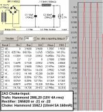
Alternatively, a choke input circuit can be formed from a 10V 4A trafo (from JMS, or a Hammond 266L20 -- and a Hammond 159ZJ choke. this would be a kind of Rolls-Royce of a raw dc supply.
Attachments
Thanks a ton Rod,Hi Clive,
I recommend short wiring from trafo-rectifiers-caps, because long wires (which carry the heavy pulse currents) will risk coupling to the signal wiring.
If you buy a 7,5V rms trafo, you can use the standard CRC raw dc circuit - this is given in detail in the application notes (please click my name -> send email for the PDF documents).
Alternatively, a choke input circuit can be formed from a 10V 4A trafo (from JMS, or a Hammond 266L20 -- and a Hammond 159ZJ choke. this would be a kind of Rolls-Royce of a raw dc supply.
I'll measure up how close I can get the heater outputs to the 2A3 sockets, my initial estimate is that I should be able to arrange things so the heater wire to the valves are about 50mm to 60mm, it this ok? The trafo wiring can be really short, far shorter than it would be if it used the TRAM trafo.
If I go this more expensive route, I would I hope derive benefits from the choke input PS and by reducing the load on the TRAM trafo. Given that a DHT preamp is a very sensitive beast I'd hope any improvement would be audible. Of course I'd never know as I can't do a side-by-side comparison. If the improvement is likely to be debatable then I might as well stick with a single chassis which would look more attractive - overall sound quality is the more important factor.
Hi Clive, provided the filament wiring avoids running too close to power transformers, the length can be 200mm. The only risk is picking up common-mode EM radiation, so in quiet locations, it can be longer still. The Regulator stability (with the rev 4 design) is completely independent of cable length.
Use fairly heavy cable, and twist lightly.
It's hard to predict whether the choke input will improve the preamp - the difference will not be on account of the filament supply, so much as the improvement in the B+ supply, where the filament rectifier recharge pulses will no longer be coupled into the trafo, and indirectly into the signal wiring. And you are right, a DHT amplifier in a high resolution system can highlight almost any improvement!
Thanks a ton Rod,
I'll measure up how close I can get the heater outputs to the 2A3 sockets, my initial estimate is that I should be able to arrange things so the heater wire to the valves are about 50mm to 60mm, it this ok? The trafo wiring can be really short, far shorter than it would be if it used the TRAM trafo.
If I go this more expensive route, I would I hope derive benefits from the choke input PS and by reducing the load on the TRAM trafo. Given that a DHT preamp is a very sensitive beast I'd hope any improvement would be audible. Of course I'd never know as I can't do a side-by-side comparison. If the improvement is likely to be debatable then I might as well stick with a single chassis which would look more attractive - overall sound quality is the more important factor.
Hi Clive,
The wires from the DHT regulators to the tube sockets must be short because they are -basically- in the signal path. But it's the wires from the transformers, to the rectifiers and from the rectifiers to the first set of cap's that are really critical regarding ripple currents = noise... ((EDIT... Ups, just noticed that Rod has also replied on this))
The load on the Tram II trafo is no problem. I think that the transformer cover is (something like) 40 degress or so after several hours of operation with 2A3 tubes.
I'll stack the Tram on top of the identical phono chassis to judge the looks. This will probably be the deciding factor as to which route I go. The separate trafo seems like it ought to be a benefit but whether it's worth the effort and expense is hard to assess.
I can't see why a separate trafo should be a benefit, but it's not worse than using the existing one as long as the wires are short.
The Tram and the phono stage can look nice when stacked (I know)
") What you should consider is that you will have to bolt the two together so they form one unit. Having cables out the back of a power supply box, through cables to the preamp box, and then running through the preamp box is a no-go. If using a separate box the wires should go straight up from the box under the Tram...
What you should consider is that you will have to bolt the two together so they form one unit. Having cables out the back of a power supply box, through cables to the preamp box, and then running through the preamp box is a no-go. If using a separate box the wires should go straight up from the box under the Tram...Personally I think it's much better to have everything in one box, with short connections - but that's just me.
I would bolt the 2 chassis together to form one box, I would also cut large holes in the top to the PS chassis to let air through to the top chassis and out via the tube sub-chassis. There would be zero external wiring, it would all go through the large holes I would cut.I can't see why a separate trafo should be a benefit, but it's not worse than using the existing one as long as the wires are short.
The Tram and the phono stage can look nice when stacked (I know)
Personally I think it's much better to have everything in one box, with short connections - but that's just me.
The wring to from the trafos would be shorter than if I used the TRAM trafo.
What am I missing here? This seems like a technically marginally more optimal solution and Rod feels there could be some benefit due to the heater recharge pulses not being coupled to the other windings in the TRAM trafo.
I would bolt the 2 chassis together to form one box, I would also cut large holes in the top to the PS chassis to let air through to the top chassis and out via the tube sub-chassis. There would be zero external wiring, it would all go through the large holes I would cut.
The wring to from the trafos would be shorter than if I used the TRAM trafo.
What am I missing here? This seems like a technically marginally more optimal solution and Rod feels there could be some benefit due to the heater recharge pulses not being coupled to the other windings in the TRAM trafo.
I don't think that you are missing anyhing Clive. Notice that Rod does not say that it will be an improvement. He says that it's hard to predict, and that it might...
Again: If you like two chassis bolted together to form one unit and can keep the wiring short etc, then that will be a good technical solution and it will work well for sure. For me personally that's a technical/mechanical solution trying to fix a problem that is not there, but that's just me according to my priorities. You make your design of the DHT implementation according what you think is the best solution. That is the beauty of DIY
One thing is sure though: The improvements in both sound quality and noise performance is -more than-worth the effort..!
Last edited:
I take your point that the 2 chassis thing could be a solution looking for a problem. I just wanted to go through the process of thinking is through fully. I'm not wedded to the extra expense and work!I don't think that you are missing anyhing Clive. Notice that Rod does not say that it will be an improvement. He says that it's hard to predict, and that it might...
Again: If you like two chassis bolted together to form one unit and can keep the wiring short etc, then that will be a good technical solution and it will work well for sure. For me personally that's a technical/mechanical solution trying to fix a problem that is not there, but that's just me according to my priorities. You make your design of the DHT implementation according what you think is the best solution. That is the beauty of DIY
One thing is sure though: The improvements in both sound quality and noise performance is -more than-worth the effort..!
I suspect I'll end up going down your route.I take your point that the 2 chassis thing could be a solution looking for a problem. I just wanted to go through the process of thinking is through fully. I'm not wedded to the extra expense and work!
Thinking everything through is always the good thing to do. And I'm not saying there is one right way to implement these regulators in a Tram II. It's always looking for the best compromise. Things to consider on the two-box-bolted-together-as-one-unit route that are not related to the technical side of the two box solution are for instance:
What will happen with resale value? I think it will go down quite a bit on a Tram II that no longer looks like a Tram II and is based on two boxes with all kinds of holes cut in them.
How can decoupling be made in an efficient way that does not compromise the sound? (A box on top of a box is usually a bad solution sonically).
Etc...
Regarding the B+ supply: Remember that in our Tram II's there is done a lot to supply a very clean and good B+ to the triodes: First there is the tube rectifier and the very effective electronic choke supply. Then the Mu-follower tube and finally the FET based CCS. Not until after all that comes the tube.
Resale's not really an issue, there would be no holes cut in the TRAM chassis, just the new lower chassis. The preamp could be returned to original spec in a few minutes.
As for decoupling, they would be rigidly bolted together via the 6 existing base plate holes, it would act as a single chassis.
The main issue is that the chances are that the benefits are not guaranteed to exist and if they do exist they may be very small.
As for decoupling, they would be rigidly bolted together via the 6 existing base plate holes, it would act as a single chassis.
The main issue is that the chances are that the benefits are not guaranteed to exist and if they do exist they may be very small.
There are never guarantees. I'm quite sure, that the benefits will be extremely small, if there will be any. Likewise the risk of a two box solution being worse sounding than a one box solution is also extremely small. But I think it's just as likely that a two-box can be marginally worse sounding as it can be marginally better... My honest opinion: No sonic difference, so choose the mechanical solution you like the best...
Well-implemented B+ conditioning will certainly reduce the chances of any difference - I was not aware the TRAM had a FET choke.
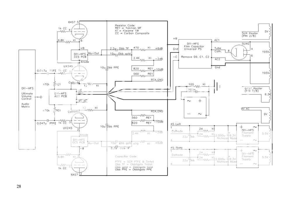
Slightly off topic here, but this is the block schematic for the Tram II. The ''DIY HFS film capacitor universal PS'' after the rectifier tube is the electronic choke supply. After that the Mu-Follower tube and the CCS
Last edited:
The use of chokes (without core or with iron core) replacing drop resistors for filament supplies isn't noval
These puppies I use for years, up to 1A. They're effective outside AF, I never did an listening test*. No cure, no harm
When distance is to be covered, I split the supply in a 'noisy part' near the transformer and a 'clean' part as close to the load as I can get.
*DHTrob reported progress with air wound coils on filament supplies.
An externally hosted image should be here but it was not working when we last tested it.
These puppies I use for years, up to 1A. They're effective outside AF, I never did an listening test*. No cure, no harm
An externally hosted image should be here but it was not working when we last tested it.
When distance is to be covered, I split the supply in a 'noisy part' near the transformer and a 'clean' part as close to the load as I can get.
*DHTrob reported progress with air wound coils on filament supplies.
Last edited:
- Home
- Amplifiers
- Tubes / Valves
- New DHT heater