Good work guys! I read a few pages of this interesting thread because I'm trying to build a new headphone amp that's using a direct heated pentode. But I'd like to ask a question regarding the specs of the filament supply. What sould the desired features be? Constant voltage, constant current, high supply ripple rejection, low impedance at the filament? I guess I'm trying to understand what the current dht heater supply addresses.
Thanks for the interest!
New (2010) Heater measures and sounds very well. Laying out the PCB today, for a short run of boards - for more tests, different filament types, etc
i need 2 PCb for my PRE
Thank
Good work guys! I read a few pages of this interesting thread because I'm trying to build a new headphone amp that's using a direct heated pentode. But I'd like to ask a question regarding the specs of the filament supply. What sould the desired features be? Constant voltage, constant current, high supply ripple rejection, low impedance at the filament? I guess I'm trying to understand what the current dht heater supply addresses.
The ideal DHT heater should:
- Supply dc.
- Control current to a limit, to prevent damage to the filament caused by switch-ON surge (might be 8 or 10 x normal) over the years. Filament breakage is a big problem in modern 300Bs.
- Reduce ripple to the smallest possible level, since filament ripple modulates the anode current (intermodulation).
- Adjust filament voltage automatically, by gently adjusting a current source. The voltage control loop must have low bandwidth to prevent the dynamic impedance across the filament getting too low.
- present a high impedance (especially low capacitance) to the power supply, to keep mains noise and rectifier recovery pulses OUT.
- present a high impedance between the two ends of the filament. I am not entirely sure why this should be, and have never found any reasonable explanation. But if you doubt whether it is true, just try current-driven heating. Then connect 1uF across the filament - all the wonderful sound suddenly disappears!
- must also present a high impedance from the filament toward the power supply. This is to keep the anode current from capacitively coupling to Earth/Ground via the wiring and filament transformer. Before I tried current-driven heating, I found that ac-heat sounded different when different transformers were used!
- A current-driven DHT makes a big upgrade in the sound - much more natural and spacious.
The 2010 version of the design is the first of mine to give automatic voltage control, and offer fine-adjustment of the voltage/current.
The PCB should be about 1.5" x 4" / 37mm x 100mm, or less if I can get DipTrace to massage it all closer!
Heatsinking will be needed. I'll make some recommendations and general design notes up, to aid application of the boards.
Hi Rod Coleman! I use last your design, it is very better for my amli use tube:
26, 45, 2a3, or 300B, I tested!
can you post your new design???
thank
hello QuangHao,
New design uses a few more parts, to give more performance (lower ripple, low noise, auto voltage development, adjustment etc)
I'll post the schematic here when I have finished polishing it!
hello QuangHao,
New design uses a few more parts, to give more performance (lower ripple, low noise, auto voltage development, adjustment etc)
I'll post the schematic here when I have finished polishing it!
That is very excellent! I love it!
Last your design, i was successful. Now it is better, it is very very excellent
Thank!
Board is ready to go out...
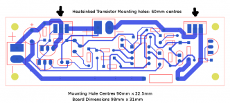
The picture shows the hole positions, layout and dimensions.
There's two TO220 transistors (isolated type) to mount to an external heatsink, with hole centres on 60mm.
Board is 98 x 31mm (about 4" x 1.25").
How does this layout fit with chassis layouts out there?
Thanks!
Rod
The picture shows the hole positions, layout and dimensions.
There's two TO220 transistors (isolated type) to mount to an external heatsink, with hole centres on 60mm.
Board is 98 x 31mm (about 4" x 1.25").
How does this layout fit with chassis layouts out there?
Thanks!
Rod
Attachments
Yes, the filament output connector is there in the middle.
The holes can accommodate the screw-terminal type connectors, or can just solder to the holes directly.
The plan was to face the connector away from the heatsink, and since there's only some 0.25W resistors in that neighbourhood, the wires should dress over them OK, I think.
Thanks for checking it out!
Regal, the measurements show 1mV or less across the filament, and even less between filament and Ground - provided you have a filament power transformer with low capacitance to ground.
A split-bobbin trafo really helps, or you can use an isolation transformer (power tool yellow trafo) if you have extremist attitude.
Either way, this should be the quietest way to heat, outside of wet-cell lead-acid battery power. (Gel cells are very noisy). Batteries present a low ac-impedance across the filament, which kills the sound.
Need to get other sources of hum out of it too, but this heater should be a big step up from ac- or voltage-regulated dc.
Member
Joined 2009
Paid Member
- Home
- Amplifiers
- Tubes / Valves
- New DHT heater