I see...I would have not been surprised if changing some components of Rod's reg from stock to something more expensive would be audible as Rod tries to hit a good price point with a very good result and much higher costs would be potentially an improvement, but only inceremental as always....?
i have read from people who reportd audible differences in changing to wiring fro the regs to the tube...other only recommend lclc raw supplies...
...would be cool to have the best of tweaks...
i have read from people who reportd audible differences in changing to wiring fro the regs to the tube...other only recommend lclc raw supplies...
...would be cool to have the best of tweaks...
Hello,
I have several power supplies which in the end all did end up in being altered to a choke input. I mean a true choke input with a minimum current related to the mH rating of the choke.
My line pre amp has a very basic lm350 regulator for heaters. A year ago i did add a choke input with a Lundahl LL1694 40mH 3 A. The lm 350 will be replaced by Coleman circuit.
Most circuits i use have shunt power supplies and all did have chokes in the power supply in CLCLC. All have been changed into LCLC.
Taking care of enough current through a bleeder.
Greetings, Eduard
P.s it seems R1 is getting hot so spending a few $ or Euros on Mills is a pretty cheap improvement.
It could be that other parts could be improved too.........
Attachments
I see...I would have not been surprised if changing some components of Rod's reg from stock to something more expensive would be audible as Rod tries to hit a good price point with a very good result and much higher costs would be potentially an improvement, but only inceremental as always....?
i have read from people who reportd audible differences in changing to wiring fro the regs to the tube...other only recommend lclc raw supplies...
...would be cool to have the best of tweaks...
Some real effort has gone into making the Regulator as isolated as possible from the filament; each version has found ways of improving this a little. This is a product of circuit architecture, choice of impedances, and importantly, layout of the PCB. Most of the components are well-buffered away from the music, and should make little or no difference to the sound.
As a result, I run my V7s in my best system using exactly the same parts as come in the kit.
It's possible that R1 will have an influence though, since it handles the heating current. It's easy and low-cost to experiment with these, but I doubt that the other parts are worth much effort.
Enjoy the DHT sound....
Hello Rod,
The differences of '' heating up '' the 5687 tube with '' standard quality components '' or over the top parts could be small.
I have been using well developped shunt supplies ( Allen Wright and Guido Tent) and installing choke input alwas has been benificial. Of course with DHT improvements will be bigger. The extra cost of Mills is minimal.
Your boards did not arrive today ( you must be in a real remote area) so will order some Mills today in the Uk. Normally during working days i am not willing to diy in the evening lol.
It would be nice if you offer future customers to pay a little extra for Mills instead of the standard resistors.
Already have the Tent dht supplies for my future VT25 amp dont know if yours and his are comparable?
greetings, Eduard
Hello,
I did some test with my present EI split bobbin heater transformer ( which has deveral secundairy taps)and choke input power supply with SBYV-28-100 diodes with the right bleeder for the choke and a bleeder giving the actual load including the bleeder. Will add a RC network with probably 1 ohm to get closer to the desired dc input voltage needed for my circuit.
I did ask Rod by email if there are any downsides of using high value of 1 ohm besides heath. Could use also use 0,47 ohm in both wires going from one cap to the other.
Will share info here if it could be used by other members.
Greetings, Eduard
Hello,
It took more time than expected to install the boards!!.
NOW i have both boards being fed by a choke input power supply. 40 mH 22000µF ( with 39 ohm bleeder) 0.22 ohm in negative and positive lead and then final 22000µF feeding two boards. Both boards loaded by a 6.8 ohm 25 watt and trimmed to 6.2 volt output. Input voltage to the board is 11,4 volt. Voltage drop across 0.22 ohm is 340 millivolt if i remember well. I could skip one of them but probably i will just leave it like that.
The only thing getting hot now is the 39 ohm 12 watt Mills bleeder about 80 degrees but will be higher with chassis closed.
R1 and R2 around 40 degrees, two transistors on heatsink 30 degrees
I thought RV1 would have a kind of stop haha. So i will just turn back 15 turns before installing the 5687 tubes. Tomorrow i will connect the tube sockets.
I will connect them ( left/right) identically. Pos and neg to the same pin on the tube socket.
greetings, eduard
Hello,
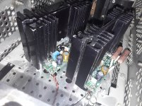
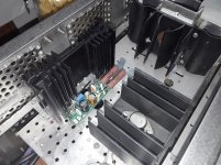
Forgot to include to photos.
One is the new regulator and the old lm350 for two 5687 tubes.
The other one each 5687 it's own regulator. Now still wired to a25 watt resistor for testing. Nothing reaches more than 40 degrees Celsius except the 12 watt mills bleeder
Greetings,Eduard
P.s yes the heatsinks are big but I had them in stock. It was not 100% clear if the smaller ones I had would be big enough. Most electronic parts will cease to exist because of exposure to heat.....
Attachments
Seems like major overkill to me. Since the 5687 is an IDHT. Have you found that it makes a difference in the sound quality?he other one each 5687
Seems like major overkill to me. Since the 5687 is an IDHT. Have you found that it makes a difference in the sound quality?
Exactly. Now you've implemented Rod's regs, why don't you change out the 5687 to a DHT? You won't get a gain of much more than 9 to 11, e.g. with 4P1L or 2P29L, so needs a rethink of the circuit, but you'll be starting on the right path.
Hello,
Tubes not connected yet.
Overkill surely but if it can improve for a few euros it will be beneficial.
5687 will be improved a little not as much as a what for sure.
But changing into choke input for th lm350 was also a big improvement.
We will see .
Of course everybody here should switch to high efficiency drivers.
Greetings,
p.s Dht with mediocre speakers will still sound mediocre
Hello,
Not sure yet But it seems switching to choke-put with the lm350 regulator was a bigger difference than switching from the lm350 to the coleman both with choke input.
I understand with a DHT changing in the heater supply will give bigger difference.
BUT the Coleman is cheap compared to a more regular heater supply.
Greetings, Eduard
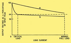
Changing from Cap-input to choke-input can reduce the noise coupling from this dc supply to other (more sensitive) parts of your system, like the DACs, or MC preamp stage - and that could give a better overall sound.
as Andy says, you're now in a good position to compare the range of useful DHTs for preamp duty - 4P1L is certainly a good start, and there's plenty of build guidance over at the 4P1L preamp thread.
as Andy says, you're now in a good position to compare the range of useful DHTs for preamp duty - 4P1L is certainly a good start, and there's plenty of build guidance over at the 4P1L preamp thread.
I am using a raw supply (845 Coleman reg) that consists of a 5A LT338 regulator board from Audiowinds 5AMP 1.5-32V Adjustable Voltage Regulator Module, LM338 | eBay
I put 100 Ohm across it to give a resistive load. It works fine but have thought about building a choke input passive supply. Any thoughts? Do I get the full benefit of the Coleman board this way? I was using the board to directly supply the filaments before.
I built a choke input supply for 4P1L Coleman boards on my filament bias preamp.
One good thing about using a regulated raw supply is you can set the voltage for minimum and unvarying dissipation at the coleman board. I find this set up to stay cool, but it's not summer here yet! An easy way to mount the board to the chassis is to cut a small square section of aluminium and drill / tap one end and side.
An externally hosted image should be here but it was not working when we last tested it.
Last edited:
hello,
You will need a big choke like the Lundahl ll2733 with two coils in parallel to withstand the high current needed for the 845 and you will need another transformer for sure.
And i would install a bleeder resistor to take care of the minimum current needed to make it work as a choke input.
greetings, erduard
Any advice rgds the delay period for filament heating on 845? Does it damage the cathode if the B+ comes on first? eg as with a DH rectifier tube. I have always used a pre-heat sequence but no longer practical (for other reasons). Given that the high initial voltage is within components spec. Thanks.
Last edited:
Hi Dennis,
The PP [regulator] board is designed to work with two DHTs running from the same supply - this is normal for PP, but for SE we normally use 2 independent supplies - else the cathodes for Left & Right would be joined.
I have seen Western Electric shema's where batteries were used and the two sides of stereo in SE and were using the same battery!
So what is detrimental [the no-go area] if we use one supply for both sides' DHT with fixed negative bias?
With two filaments operating directly in parallel, and with the "cathode" connected to the same point, the triode will still function.
But please remember that the filament voltage produces a skew of (effective) bias across the length of the filament. That's to say that the bias is +5V higher at one end of the 300B filament, compared to the other. This in turn produces a skew in the gm of the triode, with higher gm at the region of the filament with lower effective Vgk.
And with this skewed gm comes a (music) signal across the filament. If you run two DHTs in parallel, think about how different signals in the anode current will mix, with the two signals shorted together.
Then again, with a battery (or voltage regulator, or electrolytic capacitor) you short the signals out anyway.
Any of the above short circuit processes crushes part of the signal, and the sound suffers for it - especially the stereo spatial quality.
I can best advise that constructors build it correctly - at least once - so that you can really compare alternative approaches - dc ac, or battery. There's no substitute for experience.
I used to see from time to time, schematics where the cathode connection was through a split cathode bias resistance with higher R from ground to the plus voltage end of the filament in an attempt to even out the cathode current emission from end to end. If I recall correctly, one of your early posts on this thread had that scheme as well. (IIRC, splitting into a Y about half way up the Rk.)
I haven't seen it on any recent designs. Did it turn out to be more wishful thinking than effective design?
I haven't seen it on any recent designs. Did it turn out to be more wishful thinking than effective design?
- Home
- Amplifiers
- Tubes / Valves
- New DHT heater