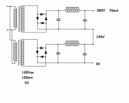
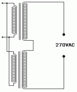
I happen to have two mains transformers that I got for next to nothing. The secondaries are a nominal 135 volt at over 100 milliamps. There are multi tap primaries. I have heard of voltage doublers and I'd be grateful if some one could explain how I can do that to these secondaries as they would then form the basis of a good twin mono pre-amp supply. I figure I should be able to get 135x2=270 volts plus some extra with the appropriate primary tap. I am aware that the ripple voltage will be the same as the mains supply but after that I'm not sure. Can someone put up an illustration please, preferably with capacitor values/ratings etc?
Hi,
A voltage doubler rectifier into a capacitive load would give you roughly twice the primary voltage at half the primary current.
Ripple voltages are much higher due to less adequate filtering so care needs to be taken to further filter it prior to feeding the B+ to the circuit.
GLASSWARE
Cheers,
A voltage doubler rectifier into a capacitive load would give you roughly twice the primary voltage at half the primary current.
Ripple voltages are much higher due to less adequate filtering so care needs to be taken to further filter it prior to feeding the B+ to the circuit.
GLASSWARE
Cheers,
A voltage doubler works by connecting a pair of diodes in opposing polarity to one end of the secondary winding, so as to maintain charge on a pair of capacitors, one negatively and the other positively, with respect to the other end of the secondary winding. The following rough schematic gives the idea.
Xfmr                diode
 ||C--------------|>|-------------  +270v
 ||C            |                 |
 ||C 135v   |                 = capacitor 220uF
 ||C            |                 |
 ||C------------------------
                  |                 |
                  |                 = capacitor 220uF
                  |                 |
                   -----|<|------------  0v
                        diode
It relies on each capacitor retaining its charge long enough so that its voltage doesn't drop significantly between charging pulses, which occur one each mains cycle (i.e. 50 positive and 50 negative pulses per second). The values of 220uF shown in this example should be more than adequate for your purposes.
All this energy has to come from somewhere, consequently what you gain in volts you lose in amps. Your 135v 100mA transformer will be able to provide ~270v but at only 50mA max. However, for most preamps I've seen this should be enough.
The voltage doubler produces 50htz ripple and should be followed by a good filter.
Sorry about that bl**dy mess! I spaced it all out properly but the typing collapsed when I submitted it. Basically:
1. Connect one end of the transformer secondary to the junction of a pair of electrolytic capacitors diodes in series.
2. Connect the other end of the secondary to the junction of a pair of diodes in series.
3. Connect the other ends of the diodes to the other ends of the electrolytics, observing correct polarity.
4. Take the output of the voltage doubler from the ends of the electrolytics.
Thanks all. Yes I'm up to speed on VA ratings. Frank, I take it that what you have refered to as the "primary" is what I assume is the secondary (of the transformer) IE the primary is the mains side and the secondary is the winding prior to the rectifier. Any way I think I'm clear now. Ray moth your written explanation will make sense of a diagram I have. Thanks.
There are several ways to make voltage doublers. On this page http://www.du.edu/~etuttle/electron/elect9.htm some of the most common are shown, full wave, half wave and multiplier type. The fullwave type gives much lower ripple as the ripple frequency is 100Hz but the disadvantage is that both inputs are floating but it doesn't matter so much with transformer coupling.
There are another variant using a bridge rectifier which seems to be less popular but it has an advantage if you want to make a circuit that i easily switched between ordinary rectification and voltage doubling, one example is here http://sound.westhost.com/project65.htm
Regards Hans
There are another variant using a bridge rectifier which seems to be less popular but it has an advantage if you want to make a circuit that i easily switched between ordinary rectification and voltage doubling, one example is here http://sound.westhost.com/project65.htm
Regards Hans
ray_moth said:Code:Xfmr diode ||C--------------|>|------------- +270v ||C | | ||C 135v | = capacitor 220uF ||C | | ||C------------------------ | | | = capacitor 220uF | | -----|<|------------ 0v diode
Let's see if the CODE tag helps. If not, hit QUOTE on this or his post to see how it was typed.
The hum output from such a doubler is 120Hz. It's a FULL WAVE doubler. One ''up" pulse to the top cap followed by a "down" pulse to the bottom cap, due to the connection the phases are equal and they both go up.
Does your transformer have a center tap? Have you been using it FWCT? (Typically for tubes; one diode on each 'arm' of the winding, pointing towards the first filter cap, which is grounded to the CT.) If so, just put a FWB (SS or if you want to be annoying, damper diodes) on it and go. Double voltage, half current.
Which reminds me, multipliers are tough on transformers so you'd be wise to derate the current draw a bit. Although, the winding is used in the same way so I suppose it wouldn't be too much worse than the standard RMS 1.5-2x derating used with FWCT or FWB rectifiers.
Tim
Just a little drawing could help 
An externally hosted image should be here but it was not working when we last tested it.
by the way... because a voltage doubler gives a ripple at double frequency to mains, it will need less filtering compared to normal mains frequency to get ripple down to same level, but you may find that the higher freuqncy is more noticeable and more anoying, and will need heavier filtering after all.
benny said:by the way... because a voltage doubler gives a ripple at double frequency to mains, it will need less filtering compared to normal mains frequency to get ripple down to same level, but you may find that the higher freuqncy is more noticeable and more anoying, and will need heavier filtering after all.
this is the one area in which a regulated HV power supply helps a lot -- the old Heathkit variable HV power supplies used a voltage doubler to yield 600 VDC -- this was then regulated -- in the early devices with a tube error amplifier and a bunch of 6L6GC's as the pass elements. generated enough heat to warm up a slice of pizza.
i don't know why they just didn't use a trafo which had the correct winding -- maybe they had a bunch left over from some deisgn.
Or most probably for cost consideration, tranny is simpler to wind !i don't know why they just didn't use a trafo which had the correct winding -- maybe they had a bunch left over from some deisgn.
Yes a full wave voltage doubler gives ripple at twice the mains frequency the same as an ordinary full wave rectifier.because a voltage doubler gives a ripple at double frequency to mains
No it needs more filtering than an ordinary fullwave rectifier, the caps need to be twice as big for same percentage of ripple.it will need less filtering compared to normal mains frequency to get ripple down to same level
As alreday described a doubler doesn't give higher frequency than a full wave rectifier and iit is actually much easier to smooth 100Hz fullwave ripple than 50Hz halfwave ripple. half wave doublers are really terrible and a pain to make working in a good way.but you may find that the higher freuqncy is more noticeable and more anoying, and will need heavier filtering after all.
Regards Hans
Follow the doubler cap. stack with a LC combination. You want an inductor with a reasonably low DCR. The setup is an "extended" pi section filter. GOOD PSUs have been made with a full wave doubler followed by a LC combination. The superb H/K Cit. 2 uses such a PSU.
It is in the nature of things that the full VA rating of a trafo is NOT available when capacitor I/P filters are used. The trafos in question are rated for 100 mA. RMS. 25 mA. of DC from each doubler is a realistic expectation. That should be plenty for a single channel of a preamp.
If you can get them, the Cree 600 PIV Silicon Carbide (SiC) Schottky diodes are a GOOD choice. Unlike PN junction diodes, Schottky diodes are switching noise free.
- Status
- This old topic is closed. If you want to reopen this topic, contact a moderator using the "Report Post" button.
- Home
- Amplifiers
- Tubes / Valves
- How do you double the voltage on a PSU?

