Hi guys!
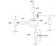
I am seeking for a tube preamplifier for my output amplifier (Onix OA601). I have made something like 20 versions of a line stage using 5687. Configuration using srpp in first stage and white cathode follower in second stage was o.k., config. using anode follower in first stage and cathode follower in second stage directly coupled was o.k. but the best config. seems to be the simplest one stage anode follower. First two configurations didn't gave me any problems with hum but the last one is driving me nuts. I have tired everything I found on net about removing 50Hz hum and nothing helped. The last schematic is attached. As You can see the schematic was found somewhere in the net and it is not new. I have used one tube (half of it to be precise) for one ch. and one tube for the other.
I have tried two triodes in paralel, tried to filter the heating for tubes ( on tubes pins directly- that helped a lot), and nothing helped to completely remove the hum- now I have still some hum so I can listen to my preamp but it is humming to much to let it that way. My grounding is stargrounded at the input chinch ground. Need help......
regards
daniel
Attachments
1)Have you tried multiple star grounds?
i.e. power supply grounds at one point, cathode resistor grounds at another, signal grounds at another - then bring the grounds together at one point. Works for me.
2) Also are your filements grounded at one end? I would try floating them at 40V or so, might quiet them down.
Easy way is to calculate a 2 resistor voltage divider off the B+, put a cap across the second resistor to ground, and connect one end of the filaments to the junction of the resistors at +40V or so. Make sure there is no ground connection or they will glow very brightly!
3) What is your power supply? Does it have decent filtering?
the best config. seems to be the simplest one stage anode followe
yes indeed. of course anode follower is not a correct term but i agree with your experience. the 5687 sounds even better with a choke load to my ears.
Sorry for asking an obvious question but are the heaters grounded?
Hi!
The heaters were previously at 60Vdc because of my previous experiments. Now they are grounded at the last filter cap. Also tried grounding it at the transformer secondary (I have two 7Vac secondaries- grounded it in the middle).
Didn't try multiple star ground- will try it later today.
I have thought about my HT- I have EZ12, 16uF first cap, huge inductor (don't ask me for the value I didn't measure), 47uF, and RC-RC and bleeder in paralel with the last C. R=250R, C=100uF. Maybe this is not enough. Will try today to put 330uF as the last cap.
regards
daniel
p.s. This is only a prototype- I'm trying to make something really good with 5687 and the best way is to experiment with different topologies. The best that I have found is the topology above- and it is simple to.
analog_sa ; How big is the choke in Your setup?
huge inductor
The huge inductor might mean that it is a high current/ low inductance version. You would need to draw poweramp currents to get the choke to "work". Try a 20k bleeder resistor 10 watt or higher AFTER the choke to suck some more current through the choke...and see if that improves the situation.
Cheers,
Bas
Hi!
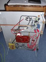
Mr. "Huge" is in this case 4000 turns with 0,3mm diameter wire (please look at the pictures- it is double C iron - the smallest of all irons - hugh?!- how can it be the smallest one ) - I know that huge doesn't meen anything but a little bit bigger inductor (that I have measured) turned to be 120H iron with 7mA. That was the highest current I could get when I measured it.
So I didn't measure this one- I think that it might be from 20H to 50H. So I supose it is big enough for this application....
thanks for the advice - will try it later today. Although I think that with 40mA total current draw (in my previous applications) I have had the same amount of hum as in this application (somewhere around 30mA total current)- so I think it won't help but I must try everything... since I don't know any more what to do.....
Mr. "Huge" is in this case 4000 turns with 0,3mm diameter wire (please look at the pictures- it is double C iron - the smallest of all irons - hugh?!- how can it be the smallest one
) - I know that huge doesn't meen anything but a little bit bigger inductor (that I have measured) turned to be 120H iron with 7mA. That was the highest current I could get when I measured it.So I didn't measure this one- I think that it might be from 20H to 50H. So I supose it is big enough for this application....
thanks for the advice - will try it later today. Although I think that with 40mA total current draw (in my previous applications) I have had the same amount of hum as in this application (somewhere around 30mA total current)- so I think it won't help but I must try everything...
since I don't know any more what to do..... Class A SE topology
Class A SE topology is not forgiving of power supply hum and noise.
To determine if that is the case measure the AC voltage on your DC plate supply, using a scope or multimeter set to AC volts,if it exceeds what you can tolerate try the following:
Place an inductor on the output of the PS and follow it with the largest cap you have availible for that voltage level.
Conect the plate resistor to the cap.
If an inductor is not availible you can substitue a resistor start with a 100 ohm 10W.
Hi!
Those previous topologies that I have used had better power supply noise suppresion- I guess that my HT might be that devil inside.... Well some cap's and things would do the thing if this is the case.... thatnkx to all- let You know 'bout that later today after I have tried it...
thanks
daniel
Those previous topologies that I have used had better power supply noise suppresion- I guess that my HT might be that devil inside....
Well some cap's and things would do the thing if this is the case.... thatnkx to all- let You know 'bout that later today after I have tried it...thanks
daniel
I may be wrong but I would try true point to point wiring instead of the PCB combo you are using. Granted, I have never attempted ( yet ) a preamp but I have always had good luck with a common ground buss. I use 17 gauge silver wire for the buss and I raise the heaters above ground ( as previously suggested ) by about 35 volts or so. I really like the layout that was used on the Decware Zen amp and have adapted it for the two amps I have built. I have heard of one other person having problems with humming in a 5687 preamp though. Look here: http://www.netaxs.com/~vkalia/5687.html and you may find some valuable info. I would not, however, recommend that you use the sloppy wiring technique that he used .
.Guys thanks- problem solved.....
I must say that this tube is so sensitive.... Problem was laying in to small cap's in my HT power supply (I have only one inductor- for this tube this is "only")- 600uF is now playing in my HT power supply. Also I have grouped the grounds as suggested before- but a little bit different connection than suggested. That took the problem for good. O.k. - thanks for Your help - now I have to do the line as I have intended to- double the triodes and let them play in 6.5mA/triode.
Will post the schematic later when I would be satisfied with the sound .....
thanks again
daniel
To Mr. G - this project is only a prototype- I would make it properly when I am satisified with the sound/design....
- Status
- This old topic is closed. If you want to reopen this topic, contact a moderator using the "Report Post" button.
- Home
- Amplifiers
- Tubes / Valves
- 5687 pre?