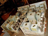
Check out this photo of four chassis, a few hundred pounds of vintage iron, four 3B28 rectifier tubes in each PSU and transformer driven 809 DHT P-P output pushed by a pair of P-P 6L6's in each. The easiest first mod is to drop in a pair of 811A's.
If anyone has the schematic for the FRT-502 AM VHF base station circa early 1950's I would very much appreciate receiving a copy.
Cheers,
Rob
If anyone has the schematic for the FRT-502 AM VHF base station circa early 1950's I would very much appreciate receiving a copy.
Cheers,
Rob
Attachments
 Awesome, where did you pick those up?
I got two of the complete transmitters in crates government surplus about 10 years ago. They were each in a very heavy steel rack cabinet and weighed about 800 lbs each. I stripped them and kept the pwr supply moules and AM modulators. One RF deck is still intact (used two 829B's as exciter and final). I actually put one of these on the air for a brief period with music when I got them just to play. Just the leakage into a dummy load could be picked up by my portable aircraft band VHF receiver for a 1/4 of a mile.
The output transformer would have to be changed as it has a hi-Z output winding meant to modulate the B+ line to the tube final.
The xfmers are all oil filled. Vitamin-Q oil and paper caps everywhere, etc. The best quality tube components everywhere.
If I were to make a plasma speaker which is on my long list of projects, then this output transformer would be useable as-is to modulate the RF power oscillator B+.
B+ looks like probably in the 900 volt range.
FRT-502
Did you ever get the manuals on the frt unit?
I have one of these, actualy part of onel.
The power supply and the modulator.
I plan to use the P/S on one of my receivers. I really have only one question:
Does the P/S run on 220v or 110?
I suspect 220 with the 4 3b28's in the circut.
Thanks. Please e-mail me off list at usa_military_radio_doc##tor@adelphia.net
(Remove the ##'s)
Thanks !!!
Hey Doc,
I have not yet been successful at finding any schematics or other documentation for this transmitter.
The primary on the PSU is 120 VAC, 60 Hz. This makes it perfect to set up for domestic use as a audio amp or whatever.
With all those xfmers it would make a good theft resistant electric space heater!
RadioDoctor said:Thanks, I'll just dig in..and hope the majic smoke stays in..
FYI, there was a chassis rack panel that was a unit cooling blower with a squirrel cage and a 1/4 HP induction motor mounted immediately at the bottom of the rack beneath the PSU. I cannot remember offhand if the master Heinemann ckt breaker/power switch was on the blower chassis panel, or is on the PSU. I could find out as I still have the blower units.
If you end up circuit tracing I would really appreciate a copy of the schematic you come up with.
Thanx and good luck. I`d like to make a nice pair of push-pull triode monobloc audio amps with my pair someday if I don`t offer these for sale. They will support a P-P pair of 811A`s very nicely. Too bad of the limited frequency response of all the audio iron. I wonder if there might be practical work arounds. The circuitry around the ouitput stage looks good. P-P triode output driven by interstage xfmer that forms phase splitter also. P-P 6L6`s drive the IT. The linput stage is definitely lo-fi being set up to power a carbon microphone. That would have to go.
The PSU would have enough extra jam since the RF deck was not being used, to supply a healthy triode RF power oscillator being plate modulated (with the FRT`s modulation type Hi-Z secondary output xfmer) to drive an experimantal plasma loudspeaker cell. Dang, I`m getting excited about building this ....agan.

RadioDoctor...any progress?
Hi Doc,
Did you get any farther with your FRT502 PSU unit? Traced a schematic perhaps????
Thanks, I'll just dig in..and hope the majic smoke stays in..
Hi Doc,
Did you get any farther with your FRT502 PSU unit? Traced a schematic perhaps????
You should ask there: http://amfone.net/Amforum/index.php
May be some of AMers would suggest you to swap output transformers: they can give you some with speaker outs, you give them yours, for a plate modulation.
May be some of AMers would suggest you to swap output transformers: they can give you some with speaker outs, you give them yours, for a plate modulation.
You should ask there: http://amfone.net/Amforum/index.php
May be some of AMers would suggest you to swap output transformers: they can give you some with speaker outs, you give them yours, for a plate modulation.
Thanx for the lead on that AM'ers group. I'll try that!
I may not want to drive speaker voice coils with these. I may wish to high level modulate a class-C power oscillator running at 28 MHz to drive a big plasma speaker all the way down to woofer crossover point. If so, the present output iron would be useful. These modulators are kinda special and IMO ought to end up doing something 'special'. Many folks have tube amps. No-one I know has high level modulation RF plasma in their sound system.
You should get huge plasma flares to match power of such modulators!
Well actually not nearly so much as you might think. These are 50 watt RMS modulators (rating stamped on the output xfmers) using P-P 809 triodes. They were designed to conservatively modulate a 829B which was making about 70-80 watts CW. In theory I could modulate a power oscillator with as much as 100 watts RMS output.
At 27 MHz, 100 watts of CW RF won't be capable of making a very large 'flame'. I'm gonna guess no more than maybe 1/2 inch long. I anticipate that the flame will have to be horn loaded to the listening room.
Interesting project!
Are you going to post pictures of the process?
Interesting project!
Are you going to post pictures of the process?
Sure I will, if I ever get a round'tuit. As you know, those are pretty hard to find. I've got some projects on the go now that are real time consumers and which I feel are much higher priority. For example a few years ago I mentioned that I was starting to build a very ambitious wind turbine. Well I have been enormously busy ever since doing exactly that.
For example a few years ago I mentioned that I was starting to build a very ambitious wind turbine. Well I have been enormously busy ever since doing exactly that.
How is it going?
How is it going?
I'm three years into it now and have it about 75% done. Still need to make four airfoil blades and do a bunch more welding. This project was an enormous challenge for me, especially for one person, not well, working all alone. See some pictures and description here.
http://www.microcogen.info/index.php?topic=59.0
Still looking...
Still looking for PSU chassis and Modulator chassis schematics for the FRT 502.
Some progress has been made. A week ago I found a friend who was happy to take one of my rack cabinets from this pair I have to display a part of his military radio collection. What I desire to implement ought to fit in the remaining rack, although making amplifiers that require a forklift to move may not be the best idea for home use.
Any assistance with this still appreciated.
- Status
- This old topic is closed. If you want to reopen this topic, contact a moderator using the "Report Post" button.
- Home
- Amplifiers
- Tubes / Valves
- Field of Dreams (a pair of FRT502 modulators)