Hey, I really wannna know the amp's approx. power dissipation.
Is it really a big secret to tell?
And I don't think I'm gonna use the regulator. It'll probably just add complication to this dead simple SE amp
Can you suggest me a PS for these amps...
I've got these things that could be used for it:
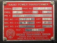
*1pcs 488VCT @70mA / 6.3V @6.2A, 64VA Potted Chicago Tranny
*12pcs 100ohm 50W Aluminium Clad Dale resistors
*Many EZ80/81 rectifiers (Inc. TFK).
*A few 5U4 and 1pcs GZ34, but wanna use'em for my next "BIGGIE" projects.
I haven't got any choke & cap yet...
I prefer not to use any choke for these amps, in order to keep things simple.
I'll buy caps later on, after the design is determined.
Oh yeah, I want to share single PS for both channels.
Cheers,
JayJay
PS: Man, sheep's eye dissection is just disgusting!!
But it was interesting though...
Did it on Friday for school biology practical work
Is it really a big secret to tell?
And I don't think I'm gonna use the regulator. It'll probably just add complication to this dead simple SE amp
Yep...Then there's the PS to consider also...
Can you suggest me a PS for these amps...
I've got these things that could be used for it:
*1pcs 488VCT @70mA / 6.3V @6.2A, 64VA Potted Chicago Tranny
*12pcs 100ohm 50W Aluminium Clad Dale resistors
*Many EZ80/81 rectifiers (Inc. TFK).
*A few 5U4 and 1pcs GZ34, but wanna use'em for my next "BIGGIE" projects.
I haven't got any choke & cap yet...
I prefer not to use any choke for these amps, in order to keep things simple.
I'll buy caps later on, after the design is determined.
Oh yeah, I want to share single PS for both channels.
Cheers,
JayJay
PS: Man, sheep's eye dissection is just disgusting!!
But it was interesting though...
Did it on Friday for school biology practical work

Power Supply Design
Here is the Spec Sheet for the EZ80
http://tdsl.duncanamps.com/pdf/ez80.pdf
If you use 1 EZ80 per channel you should be OK
From the output of the rectifier place (Qty-2) 100 ohm resistors in series and a 50uF cap rated at least 330V. That should give you aprox. the 250VDC you desire. You have adiquate filiment current to handle all the tubes with the transormer you have on hand.

Hi,
Provided you stay well below Iout_max at all times it should be O.K.
IMO it is however not the wisest thing to do as chokes are commonly available and those larghish cap values are really unnecessary for building a well filtered P.S.
True but look at Iout_max for both types so look at what your requirements are in that department: the EZ81 is the tougher cookie of the two.
Cheers,
Is it OK to use 60uF with EZ80
Provided you stay well below Iout_max at all times it should be O.K.
IMO it is however not the wisest thing to do as chokes are commonly available and those larghish cap values are really unnecessary for building a well filtered P.S.
The maximum reservoir capacitance specified on my mullard data book is 50uF for EZ80, as well as EZ81...
True but look at Iout_max for both types so look at what your requirements are in that department: the EZ81 is the tougher cookie of the two.
Cheers,
Hey, can I make a summary here now....
Just to make sure that everything is correct for safety.
Power Output of each channel will be 4.2W
My transformer's HV secondary is 488VCT @ 70mA, single transformer used for both channels.
Two EZ80s are used, one for each channel.
Just for one channel:
EZ80 will be connected in fullwave rectification.
Straight after being rectified by the EZ80, one 100ohms (50W) power resistor is connected in series (is 100ohm enough?)
After the resistor connected in series, a 60uF 370VAC MKP cap is connected in parallel.
Overall, it's a Fullwave, RC filtered PS.
The transformer also has a 6.3V winding @ 6.2A, supplying 2X E80F and 2X EL84.
Is everything correct?
Cheers,
JayJay
PS: I don't want to use any choke for this amp... I just wanna make everything simple.
I'll use chokes for bigger projects coming up.
Hi,
Haven't read the thread from start to finish but if that 100R is the sole resistor in a Pi filter it's rather too low in value to be really effective. Go for something like 470R if you can spare the voltage drop.
Then, 50W? What for?
It's a SE amp so I'm sure 10W should do nicely already for a PS shared between channels.
Cheers,
EDIT: Just went back to post #1...Since your amp is basically the same as the fourth SE EL84 amp on Bonavolta's site why not take a peak at the PS used for that one?
Even if you'd go for a FW restifier scheme, current draw would be very similar anyways.
one 100ohms (50W) power resistor is connected in series (is 100ohm enough?)
Haven't read the thread from start to finish but if that 100R is the sole resistor in a Pi filter it's rather too low in value to be really effective. Go for something like 470R if you can spare the voltage drop.
Then, 50W? What for?
It's a SE amp so I'm sure 10W should do nicely already for a PS shared between channels.
Cheers,
EDIT: Just went back to post #1...Since your amp is basically the same as the fourth SE EL84 amp on Bonavolta's site why not take a peak at the PS used for that one?
Even if you'd go for a FW restifier scheme, current draw would be very similar anyways.
Since your amp is basically the same as the fourth SE EL84 amp on Bonavolta's site why not take a peak at the PS used for that one?
Well,
I'm still not familiar with valve amps, so here's a question:
As you know, in class-A SS, power supplied by PS sould be at least 4X the actual output power. i.e. 20W amp with 80W-100W supply.
What about in SE tube amps? The same?
If so, the PS suggested on the 4th of Bonavolta's site with my transformer(488VCT @ 70mA) will deliver less than twice the output power of 4.2W.
Cheers,
JayJay
Hi,
If you're using one xformer for both channels you'll end up short on voltage and current.
In case you have a pair of them you can still arrive at the operating voltages required by using a hybrid rectifier.
Don't forget that SE amps inevitably run in Class A.
IMHO it would be eaiser for you to choose a diagram and copy that than working from a powerxformer and figuring out what you can do with it. Just my opinion though...
Cheers,
If so, the PS suggested on the 4th of Bonavolta's site with my transformer(488VCT @ 70mA) will deliver less than twice the output power of 4.2W.
If you're using one xformer for both channels you'll end up short on voltage and current.
In case you have a pair of them you can still arrive at the operating voltages required by using a hybrid rectifier.
Don't forget that SE amps inevitably run in Class A.
IMHO it would be eaiser for you to choose a diagram and copy that than working from a powerxformer and figuring out what you can do with it. Just my opinion though...
Cheers,
it would be eaiser for you to choose a diagram and copy that than working from a powerxformer and figuring out what you can do with it.
It is actually harder to find transformers and capacitors with close-enough ratings, especially if you prefer exotic parts.

If you're using one xformer for both channels you'll end up short on voltage and current.
Yeah, that's what I was worried about during the whole process of planning.
Well, I guess I should go and get a new pair of transformers now.
I hope I have enough budget left to do so...
I really don't want to spend much money on this, as I will eventually have to build bigger amps.
Before spending more money I would measure the resistance on the HV secodary and if possible, check the wire guage. It is probably pretty conservatively rated, you might be able to use it with no probs at all.
Transformers are built with total VA being a factorin the ratings- ie you be able to get more than 70mA continuous if you don't use all 6A of 6.3V. Assuming you use only 3A or so, theres another 18VA that can be used by the HV.
As for power supply designs, remember with class A it will draw a fairly constant current, which is a nice easy load on the transformer. You don't really need much spare capacity with class A, only with AB.
I would definitely breadboard it with several dummy loads and see if the power transformer gets hot. If it doesnt then its probably all right! I would just go ahead and use it, but thats just me...
It is probably pretty conservatively rated, you might be able to use it with no probs at all.
Hey, the transformer is quite heavy, so I believe it'll handle both channels without much prob.
I would definitely breadboard it with several dummy loads and see if the power transformer gets hot. If it doesnt then its probably all right! I would just go ahead and use it, but thats just me...
I guess I'll just give it a try without testing. I don't really have enough time to make a test set-up.
I would measure the resistance on the HV secodary
It measures approx. 270 ohms.
Assuming you use only 3A or so,
Actually, a bit less than 2.5A in total (2X E80F + 2X EL84)
The transformer actually has 115V primary, suited for both 50Hz and 60Hz. So I'll use my stepdown transformer (of course, external) with it. Is this OK?
If you guys think that using this transformer without tesing is dangerous, I won't use it.
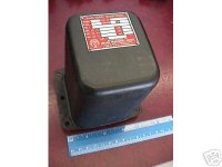
Here's are some pics:


Hey guys,
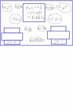
Could you have a look at my amp layout?
Is it ok?
I tried to place the E80F input tubes as far as possible form all transformers.
MKV means Siemens MKV cap.
And is it beneficial to place hybrid rectification?
I'm sorry about the wacky drawing, but my mouse doesn't move in the way that I want...
Cheers,
JayJay
PS: The diagram is not drawn to scale! there'll be a larger gap between the two E80F, giving sufficient space for airflow. And the length of gap between the two output TR as well.
Attachments
Looks fine, I have used a similar setup with no problems. Preamp tubes are fine as long as they are away from the power transformer and have DC filaments (or tightly twisted heater wires.) They will also not get hot enough for airflow to be a problem...
Why would you want to use hybrid rectification, your voltage would be too high with a bridge...
Why would you want to use hybrid rectification, your voltage would be too high with a bridge...
Why would you want to use hybrid rectification, your voltage would be too high with a bridge...
Oh yeah, I didn't think about that....
And hey, is it true that putting a 100nF from each heater terminal to ground help to reduce RF noise?
And do I really need to use wires of the gauge just enough to carry the required current for heater wire?
Of course, I'll use solid wires & twist'em tight for the rectifier HT with AC, but I'm planning to regulate the voltage for the 4 singnal tubes...
Hopefully, it'll isolate some of the noise generated by the rectifier tubes...
Cheers,
James
- Status
- This old topic is closed. If you want to reopen this topic, contact a moderator using the "Report Post" button.
- Home
- Amplifiers
- Tubes / Valves
- Help needed to find these rare values!