hi all,
how does plate current/voltage effect a tube, if at all???
i'm not talking about transconductance/plate resistance etc... but how does it effect what we actually hear???
does higher/lower voltage/current effect things like, frequency reponse, shape of/transition into clipping, noise, etc...
how does current and voltage effect these types of things, and any factors anyone might want to comment on??? firstly, how does current effect it, independant of voltage, and then how does voltage effect it, independant of current... and then, do the two interact with each other in any way?
and also, has anyone tried running a tube at below what is considered a normal voltage for that tube? for example, running a 12AX7 with a plate voltage of 60V??? what might happen here?
for this discussion if anyone replies, i am mostly interested in the effects in triodes for now.
thanks
where is it on this his site??? i have looked at this site before, and i can remember reading about running starved filaments in DHT's, but that was all i can remember that dealt with sound v's voltage, and this is not plate voltage anyway... could you point me to the right section?
cheers
cheers
Hi,
Benny,
What Woody meant, I think, was this page on Steve Bench's site:
INVERTED MODE
IMO it all depends what you want to do with the tube under those "unusual" conditions.
This is where loadlines come in handy to define the window of operation for the application you have in mind.
You can, for instance, run a 6DJ8 at very low plate voltage and very low current but you'll notice the bias voltage will also need to drop to very low voltage for the tube to work in a linear fashion within that framework...
If it's low distortion you want you'll inevitably have to stick to a zone of operating characteristics where that particular tube is linear.
Further tweaking of voltage and current will allow you to find
the "sweet spot" of that tube for your application as you're sliding up and down your loadline.
Cheers,")
Benny,
What Woody meant, I think, was this page on Steve Bench's site:
INVERTED MODE
for example, running a 12AX7 with a plate voltage of 60V??? what might happen here?
IMO it all depends what you want to do with the tube under those "unusual" conditions.
This is where loadlines come in handy to define the window of operation for the application you have in mind.
You can, for instance, run a 6DJ8 at very low plate voltage and very low current but you'll notice the bias voltage will also need to drop to very low voltage for the tube to work in a linear fashion within that framework...
If it's low distortion you want you'll inevitably have to stick to a zone of operating characteristics where that particular tube is linear.
Further tweaking of voltage and current will allow you to find
the "sweet spot" of that tube for your application as you're sliding up and down your loadline.
Cheers,
benny said:i'm not talking about transconductance/plate resistance etc... but how does it effect what we actually hear???
does higher/lower voltage/current effect things like, frequency reponse, shape of/transition into clipping, noise, etc...
Ya.
how does current and voltage effect these types of things, and any factors anyone might want to comment on??? firstly, how does current effect it, independant of voltage, and then how does voltage effect it, independant of current... and then, do the two interact with each other in any way?
*Takes another bite of breakfast cereal first*
Dig out your plate curves. Go to say... 6V6 in triode mode. Pick a random point below the Vg=0V curve. Say, 200V 30mA. (About -11.5Vg bias.) Now draw a loadline (we'll be using a transformer, as a resistor load would be more complicated), say 20mA per 100V (i.e. 5kohm). This will intersect the 0mA axis at 450V and the 0V axis at 70mA. You can see it has around -80V (intersecting the 0Vg curve at 120V) and +65V output (intersecting the imagined curve of Vg = -23V. The assymetry in these swings is 2nd harmonic distortion.
Now increase bias current. Loadline slope remains constant. Bias voltage is reduced. The effect is, your negative (that is, Vp closer to zero) swing is reduced because you are now closer to the 0Vg curve. Distortion goes down because you are operating at a higher current = more linear range, but swing is less. Since load resistance is the same, power output has dropped.
If you instead reduce current, negative swing increases because you are farther from the 0Vg curve, however, positive swing increases a bit slower because it goes increasingly farther into the cutoff region. This produces more 2nd harmonic distortion. An extreme case might be this load resistance at 5 or 10mA. You're down around -20 or 25V bias, allowing a swing of up to 50Vp-p giving a minimum peak of -50Vg. This is off the scale and can be assumed as 0mA, that is, cut off. You are now in class AB1. The output has a severely flattened top, evidence of that cutoff. Output impedance is very high in that region so it's an opportune time for another tube to fill in, hence class AB1 PP.
If you increase voltage instead of current, bias increases to keep the current constant and you move farther from the 0Vg curve. Thus you gain negative swing towards that line, but again your positive swing approaches the cutoff region. The difference of this vs. low current is that swing increases in abosolute rather than relative terms.
Reduced voltage will simply reduce swing in the same way that increased current does. Grid voltage swing is necessarily reduced, with the attendant reduction in output swing. It won't be as linear as the higher current situation, however.
and also, has anyone tried running a tube at below what is considered a normal voltage for that tube? for example, running a 12AX7 with a plate voltage of 60V??? what might happen here?
Yeah. Assuming a proper operating point (that is, one which makes approxamately symetrical voltage swing; actually, I shouldn't say that; it's a compromise between swing and distortion), which is probably something around 400 microamperes, you'll get a bit higher distortion than usual but otherwise it all scales down... Zo is higher, output is lower, drive is lower...
oh, and the other thing i was interested in was is how would a tube work if conecting the plate load resistor to earth, and biasing the cahode with a big negative voltage??? are there any advantages/disadvantages to be had?
Same thing, just like running it at 1000Vk and 1200Vp or -4572Vk and -4372Vp. Only voltage difference matters. Note grid voltage is measured with respect to cathode! Keeping it at 0V in these cases will cause some problems...

Tim
hi,
thanks to those that replied... alas, not quite what i was after... sorry, i should've been more specific.
all the loadlining stuff... already looked at it myself when i first startedt thinking about this stuff... none the less, thanks for your lengthy article sch3matic... i only browsed through it quickly, but i will read it more in depth after i write this... i never know, there might be some insight into what can be obtained from loadlines in there i never knew of that you refer to in it.
what i was more interested in was things that can't be obtained from loadlines, like how frequency response might change at different operating points, if at all... and wether a different operating point would alter noise level... and also how operating point might effect the shape/transition into distortion.. by this i didn't mean the composition of the distoriton (ie, percentage of x harmonic), but how the tube clips... does it clip harder/softer... like, how does it effect the roll into distortion... can operating point effect how hard the clipping is when transfering from below clipping into clipping teritory??? for example, assume some magical, perfect tube, so @ all operating points, we had perfectly symetrical voltage swing... can operating point effect how hard the clipping is assuming this perfect symetry if we compared the distortion at these different points at the same THD.
about the lower than standard voltage and running plate from earth while biasing cathode very negative... i wasn't asking would it work... already knew it would... but i was asking 'how' would it work... i was making reference to my questions about operating points really for the non standard lowered plate voltage about freq. response clipping shape, etc... and for the plate at zero, cathode biased more negative thing, i was thinking more along the lines of noise and anything else someone might think of... like for example, can this effect noise from the filaments much... say we floated the filaments fairly high, and biased the cathode very negative, would this give much less noise, or it wouldn't effect it enough to worry about it??
again, thanks for your replies, and thanks for the reference to the inverted triode frank, i will have a look soon... for now i reply.
by the way sch3matic... i looked at your website, and noticed you too were a school kid, and thought hey cool, i'm not the only young cat around here. good to see someone else my age that's into tubes.
cheers
thanks to those that replied... alas, not quite what i was after... sorry, i should've been more specific.
all the loadlining stuff... already looked at it myself when i first startedt thinking about this stuff... none the less, thanks for your lengthy article sch3matic... i only browsed through it quickly, but i will read it more in depth after i write this... i never know, there might be some insight into what can be obtained from loadlines in there i never knew of that you refer to in it.
what i was more interested in was things that can't be obtained from loadlines, like how frequency response might change at different operating points, if at all... and wether a different operating point would alter noise level... and also how operating point might effect the shape/transition into distortion.. by this i didn't mean the composition of the distoriton (ie, percentage of x harmonic), but how the tube clips... does it clip harder/softer... like, how does it effect the roll into distortion... can operating point effect how hard the clipping is when transfering from below clipping into clipping teritory??? for example, assume some magical, perfect tube, so @ all operating points, we had perfectly symetrical voltage swing... can operating point effect how hard the clipping is assuming this perfect symetry if we compared the distortion at these different points at the same THD.
about the lower than standard voltage and running plate from earth while biasing cathode very negative... i wasn't asking would it work... already knew it would... but i was asking 'how' would it work... i was making reference to my questions about operating points really for the non standard lowered plate voltage about freq. response clipping shape, etc... and for the plate at zero, cathode biased more negative thing, i was thinking more along the lines of noise and anything else someone might think of... like for example, can this effect noise from the filaments much... say we floated the filaments fairly high, and biased the cathode very negative, would this give much less noise, or it wouldn't effect it enough to worry about it??
again, thanks for your replies, and thanks for the reference to the inverted triode frank, i will have a look soon... for now i reply.
by the way sch3matic... i looked at your website, and noticed you too were a school kid, and thought hey cool, i'm not the only young cat around here.
good to see someone else my age that's into tubes.cheers
Yeah, seems to be a lot of us young'ins here.
Ok, so you wanted frequency response and stuff. Simple, that depends on the circuit. If you have a highly capacitive circuit (say, driving a triode output tube), max. F is determined by the Zo and C; you get an RC time constant and a slew rate.
Low frequencies are affected solely by coupling caps and inductance (transformers, chokes), something tubes typically have less control over. Feeding a coupling cap, if the tube's Zo rises - say you replace a triode (low Zo) with a pentode (high Zo) - it adds series resistance to the RC network formed by the amplifier > Zo > coupling cap > grid leak system. Typically you'll have a plate resistor so this will only have a certain maximum, and even with a zero Zo tube, it has a certain minimum. At most there will be a 2:1 difference, not really significant.
As to inductance, it depends on the value. Low values (on par with the triode's Zo at the lowest frequency of interest) will be affected much more than large inductances. This much is obvious, but contrasting situations do present themselves - 150H on a 10 or 20mA driver tube for instance, contrasted with a mere 5H in a lower quality OPT fed by a stage of say 100mA. The 150H won't very well exist except at very low frequencies, as far as the driver is concerned; however the output tube will be chugging harder at 50Hz and below due to the inductive load.
(Hmm, I'm taking a gratuitous number of words to explain something that should be simple... I must be tired again... which is hardly suprising, as my last post was 4 hours ago?)
Ok. What's next. Abruptness of clipping y'say? Doesn't really happen. Depends on the circuit too, but we'll assume your driver is chicken and can't supply any grid current, causing the overdriven peak to be flattened.
In all cases with any tube, the lower-current end of the output will ALWAYS be shorter (there is no such thing as a perfect-symmetry-output tube, it's inherent in the very physics inside them) due to the cutoff effects. As I said, higher current can be used to reduce distortion, at the price of lower swing. Swing can well be more than necessary, but if you simply dropped bias (or increased voltage) you would better utilize the tube..... You can't eliminate this though.
What's next. Um, heater bias I guess. Cathode negative, plate zero, heater zero I guess, is an ideal situation within H-K ratings. (Obviously you don't want to put -4572V on a cathode with the heater grounded in any tube besides a damper diode!) This, I presume, has lower noise due to there being no current flowing in the parasitic diode.
If the cathode is more positive w.r.t. heater, it forms a diode where electrons boil off the very hot heater and are attracted to the relatively cool cathode sleeve. Presumably this causes noise, particularly rectification of the AC heating power if used. If the heaters are floating rather than grounded, chances are in a case like this they'll float up above most of the cathodes due to this very diode effect.
^^ I say "presume" because I've never taken a noise measurement before in my life, hum noises aside. The three amps I have on right now are dead; Frankenhouse has floating(!) heaters, Hept'AU7 has one end grounded since I have a doubler tacked on for grid bias and the preamp has elevated heaters. Personally, I'll never worry about noise (of the hissing variety) until I'm working with either >100dB/W speakers or phono preamp circuits. If you stick your head in my speakers (probably somewhere in the 90dB/W range) and listen carefully, you might hear some hiss. But by that distance, you'll hear the hum too..
Tim
Ok, so you wanted frequency response and stuff. Simple, that depends on the circuit.
If you have a highly capacitive circuit (say, driving a triode output tube), max. F is determined by the Zo and C; you get an RC time constant and a slew rate.Low frequencies are affected solely by coupling caps and inductance (transformers, chokes), something tubes typically have less control over. Feeding a coupling cap, if the tube's Zo rises - say you replace a triode (low Zo) with a pentode (high Zo) - it adds series resistance to the RC network formed by the amplifier > Zo > coupling cap > grid leak system. Typically you'll have a plate resistor so this will only have a certain maximum, and even with a zero Zo tube, it has a certain minimum. At most there will be a 2:1 difference, not really significant.
As to inductance, it depends on the value. Low values (on par with the triode's Zo at the lowest frequency of interest) will be affected much more than large inductances. This much is obvious, but contrasting situations do present themselves - 150H on a 10 or 20mA driver tube for instance, contrasted with a mere 5H in a lower quality OPT fed by a stage of say 100mA. The 150H won't very well exist except at very low frequencies, as far as the driver is concerned; however the output tube will be chugging harder at 50Hz and below due to the inductive load.
(Hmm, I'm taking a gratuitous number of words to explain something that should be simple... I must be tired again... which is hardly suprising, as my last post was 4 hours ago?)
Ok. What's next. Abruptness of clipping y'say? Doesn't really happen. Depends on the circuit too, but we'll assume your driver is chicken and can't supply any grid current, causing the overdriven peak to be flattened.
In all cases with any tube, the lower-current end of the output will ALWAYS be shorter (there is no such thing as a perfect-symmetry-output tube, it's inherent in the very physics inside them) due to the cutoff effects. As I said, higher current can be used to reduce distortion, at the price of lower swing. Swing can well be more than necessary, but if you simply dropped bias (or increased voltage) you would better utilize the tube..... You can't eliminate this though.
What's next. Um, heater bias I guess. Cathode negative, plate zero, heater zero I guess, is an ideal situation within H-K ratings. (Obviously you don't want to put -4572V on a cathode with the heater grounded in any tube besides a damper diode!) This, I presume, has lower noise due to there being no current flowing in the parasitic diode.
If the cathode is more positive w.r.t. heater, it forms a diode where electrons boil off the very hot heater and are attracted to the relatively cool cathode sleeve. Presumably this causes noise, particularly rectification of the AC heating power if used. If the heaters are floating rather than grounded, chances are in a case like this they'll float up above most of the cathodes due to this very diode effect.
^^ I say "presume" because I've never taken a noise measurement before in my life, hum noises aside. The three amps I have on right now are dead; Frankenhouse has floating(!) heaters, Hept'AU7 has one end grounded since I have a doubler tacked on for grid bias and the preamp has elevated heaters. Personally, I'll never worry about noise (of the hissing variety) until I'm working with either >100dB/W speakers or phono preamp circuits. If you stick your head in my speakers (probably somewhere in the 90dB/W range) and listen carefully, you might hear some hiss. But by that distance, you'll hear the hum too..
Tim
hi tim,
thanks again for the reply.
as far as the freqency response you dealt with, you're absolutely right... especially about the simple part! A couple of minutes with a pen and paper will even give you number values on your frequency response!
alas, once again, not quite what i was asking about...
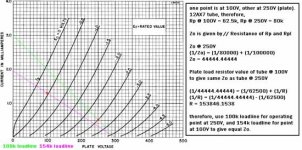
have a look at the situation i drew up for you in paint that i attatched... a couple of loadlines and a little explanation written down the side.
now, for this example, frequency response due to the output circuit is the same for both operating points, despite 150V difference in plate voltages and about .8mA in current.
this is why i am asking these kinds of questions... i am interested in what is taking place 'inside' the tube... what you were refering too was frequecny response due to the output circuit. i am interested in knowing wether a tube amplifies some frequencies more than others at certain voltages, and how inter-electrode capacitances at different operating points might effect it, and so on...
i know. that's why i refered to it as a 'magical' tube.
as far as what you said about abruptness of clipping, what do you mean it doesn't happen??? different abruptnesses of clipping can happen... one of the main comparisons people bring up between transistors and tubes... and even different tube types transfer into distortion differently... what i want to know, is within the same tube, can operating point effect how it transfers into clipping?
this is why i do worry about noise... i have never actually designed a hifi amp, and don't intend to until another day when i have money to waste on an un proven design... for now, i'll stick with what's already been proven... not on paper, but by people listening, even if i have to rely on others subjective opinions.
what i do design at the moment though, is guitar amps... in these, you are generally using 97dB or higher efficiency speakers with a phono level input signal... add to that, guitar amps are usually designed to purposefully use clipping, often in quite large amounts... the huge amounts of gain used over many stages in these designs leads to obvious noise problems. effective noise abatement methods is one area where guitar amp designers actually need to achieve a higher level of perfection than hifi amps do.
anyways, thanks for your replies, i apreciate it.
cheers
thanks again for the reply.
as far as the freqency response you dealt with, you're absolutely right... especially about the simple part!
A couple of minutes with a pen and paper will even give you number values on your frequency response! alas, once again, not quite what i was asking about...
have a look at the situation i drew up for you in paint that i attatched... a couple of loadlines and a little explanation written down the side.
now, for this example, frequency response due to the output circuit is the same for both operating points, despite 150V difference in plate voltages and about .8mA in current.
this is why i am asking these kinds of questions... i am interested in what is taking place 'inside' the tube... what you were refering too was frequecny response due to the output circuit. i am interested in knowing wether a tube amplifies some frequencies more than others at certain voltages, and how inter-electrode capacitances at different operating points might effect it, and so on...
there is no such thing as a perfect-symmetry-output tube, it's inherent in the very physics inside them
i know.
that's why i refered to it as a 'magical' tube. as far as what you said about abruptness of clipping, what do you mean it doesn't happen??? different abruptnesses of clipping can happen... one of the main comparisons people bring up between transistors and tubes... and even different tube types transfer into distortion differently... what i want to know, is within the same tube, can operating point effect how it transfers into clipping?
Personally, I'll never worry about noise (of the hissing variety) until I'm working with either >100dB/W speakers or phono preamp circuits.
this is why i do worry about noise... i have never actually designed a hifi amp, and don't intend to until another day when i have money to waste on an un proven design... for now, i'll stick with what's already been proven... not on paper, but by people listening, even if i have to rely on others subjective opinions.
what i do design at the moment though, is guitar amps... in these, you are generally using 97dB or higher efficiency speakers with a phono level input signal... add to that, guitar amps are usually designed to purposefully use clipping, often in quite large amounts... the huge amounts of gain used over many stages in these designs leads to obvious noise problems. effective noise abatement methods is one area where guitar amp designers actually need to achieve a higher level of perfection than hifi amps do.
anyways, thanks for your replies, i apreciate it.
cheers
Attachments
benny said:alas, once again, not quite what i was asking about...
Oh well... I've slept now
have a look at the situation i drew up for you in paint that i attatched... a couple of loadlines and a little explanation written down the side.
now, for this example, frequency response due to the output circuit is the same for both operating points, despite 150V difference in plate voltages and about .8mA in current.
Yup.
this is why i am asking these kinds of questions... i am interested in what is taking place 'inside' the tube... what you were refering too was frequecny response due to the output circuit. i am interested in knowing wether a tube amplifies some frequencies more than others at certain voltages, and how inter-electrode capacitances at different operating points might effect it, and so on...
Almost any tube behaves the exact same until maybe 30MHz. Some need to be derated by then, so they run much lower power by say 100MHz. You can run 6L6s at 200MHz but they're not good for much. This is mostly due to electrode inductances and capacitances, skin effect, that sort of stuff. HF tubes have several pins connected to the cathode and are well shielded (compare an 807 to a 6L6GA). If you try pushing a tube like 6C4 up to 500MHz, you won't be able to because the inductances and such simply won't allow it through. Other tubes (particularly coaxial and planar microwave types) work basically the same from DC to many GHz, although saying so isn't as easy because anything operating at that frequency will be resonant and things happen in such short times and distances that you can't always look at the circuit in terms of time across the scope or what have you. But the point being, tubes consider audio frequency as changing DC signals, almost all types can operate 3 orders of magnitude faster.
i know.
Yeah, but it's an odd thing to say because the curves are part and parcel with the 3/2 power law. Although, now that I think of it, you might be able to generate perfectly linear curves. (Or grab a 6SL7.
)as far as what you said about abruptness of clipping, what do you mean it doesn't happen??? different abruptnesses of clipping can happen... one of the main comparisons people bring up between transistors and tubes... and even different tube types transfer into distortion differently... what i want to know, is within the same tube, can operating point effect how it transfers into clipping?
Yeah, but in the case of pentode or transistors, external loop or local NFB causes it to be much more linear until it canst be linears no mores, and clips. Triodes don't have this as their internal feedback is based on that 3/2 power law. (You can set up a triode and pentode stage to have the same gain and Zo, the triode might have 5% THD while the pentode has 1 or 2%.)
But that doesn't answer your question, as you asked w.r.t. operating points. I would have to guess that, grid current aside, when pushed into the distorting areas, it will always be the same gradual figure. Only external means of additional NFB can straighten this out. Triodes do it a little gracefully due to a combination of internal NFB and its nonlinearity, indeed you can operate a triode at a higher current and get very little distortion as you are running in a more constant-Rp region. (Look at 6SL7, 6SN7 to some extent, 12B4, they all have straight curves after a certain range.) A pentode has very little NFB and hence is always distorting, though THD is still less for smaller signals. Transistors have an exponential curve and when amplifying a triangle wave, the output is known as "barn roof" or something like that, because you're applying an exponential function (the Ebers-Moll equation FWIW) to a linear signal. It looks like a barn roof!
These factors won't really change with operating point, with the exception of making things relatively smaller: i.e., say you want 20V output. That's 20% of +100V but only 5% of +400V. If the same nonlinearity exists, it will be 4 times smaller at the 400V operating point. A generalization, mind you...
- Oh, a good way to visualize that would be to draw a curve and mark a small area near zero, then mark the same width area at a higher level. Which is straghter?
what i do design at the moment though, is guitar amps... in these, you are generally using 97dB or higher efficiency speakers with a phono level input signal... add to that, guitar amps are usually designed to purposefully use clipping, often in quite large amounts... the huge amounts of gain used over many stages in these designs leads to obvious noise problems. effective noise abatement methods is one area where guitar amp designers actually need to achieve a higher level of perfection than hifi amps do.[/B]
Indeed! That's a good case for careful noise control, proper heater usage, bypassed cathodes (how can heater noise affect the cathode if the cathode can't move?
) and well filtered power supplies.Tim
- Status
- This old topic is closed. If you want to reopen this topic, contact a moderator using the "Report Post" button.
- Home
- Amplifiers
- Tubes / Valves
- does plate current/voltage effect tube sound????