but now i have some questions.
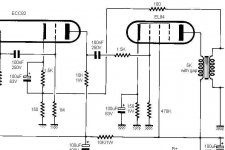
1. the feedback resistor is 100 ohm here, is it too low?
the OPT secondary is 8ohm.
2. the grid 2 is connected to B+ directly, am i need to add a resistor , say, 100 ohm to do as grid stopper.
3. there is a RC(high pass filter) network between ecc82 and el84(0.1u and 1.5k), will it affect freq. response? am i need to delete the 1.5k or place it between 470k and grid 1
can anyone help?
thanks
firstly, is this someone else's design??? or is it your own?
1) I'm guessing that this meant to say 100k... with 100ohm you'd be getting more neg feedback than you bargained for...
2) No, this is fine, depending on what voltage your B+ is... if this is how it was designed then the voltage will most likely be within the ratings of the tube... if you go adding resistors in here, you will lower the screen grid voltage, and will then change the plate curve charachteristics of the tube... not good of you want the amp to work as intended.
3) this isn't an RC filter... that cap is there to block DC and only alow AC through to the grid of the following stage... the 1.5k resistor is a grid stopper... i sugest you leave it there.
cheers
Hi,
Yep...Recognized the symbols straight away....
I'm putting my money on 10K but....looking at the rest of it it looks as if someone's been preparing a cocktail with the values of most passive components:
1K input resistance??
100nF into 1M??
Nah...don't copy that one, there's too much looking suspicious.
Here's where I found it:
EL84 SE
Cheers,")
firstly, is this someone else's design???
Yep...Recognized the symbols straight away....
1) I'm guessing that this meant to say 100k...
I'm putting my money on 10K but....looking at the rest of it it looks as if someone's been preparing a cocktail with the values of most passive components:
1K input resistance??
100nF into 1M??
Nah...don't copy that one, there's too much looking suspicious.
Here's where I found it:
EL84 SE
Cheers,
Hi,
Takashi,
How do you arrive at that conclusion?
I have my doubts about a couple of values as shown on the circuit.
Have you actually built it already?
Cheers,
Takashi,
by conclusion, the circuit will work fine without any modification and correction.
How do you arrive at that conclusion?
I have my doubts about a couple of values as shown on the circuit.
Have you actually built it already?
Cheers,
Hi takashi,
Agreed with fdegrove, some of the values are not "commonly-used".
1) Feedback resistor is 100ohm? should be in the range of xx Kohm.
2) 1st stage to 2nd stage: 100nF coupling cap + 1M? try 0.1uF + 470K.....
3) 1K volume pot?? A little bit lower than normal...try 10K (at leadt) or 100K.
4) 1.5K resistor to grid of EL84: You can simply remove it...you can add it after finishing this amp.
Correct me if I'm wrong. Thanks!
Mr. Stone
ok,
firstly 0.1uF and 100nF are the same.
u is 10^-6
n is 10^-9
also, 1M would be fine... difference if you used a 470k resistor is you would get a slightly lowered gain from the first stage, and slightly less resistor noise.
even better, try 500k or 1M
No, this is a pretty bad idea, especially with a neg f/back loop encompasing this stage....
this resistor here limits grid current... in the case of a peak in your signal causing overload on the grid, causing grid to become positive and you will have DC current on your grid... this resistor limits DC current on the grid in a case like this.
what happens is you will hear a noticeable break in sound, followed by distortion as the tube recovers. this is called blocking distortion... the effects of blocking distortion are even worse when there is a f/back encompasing this stage, as when you have no signal, you obviously have no feedback... feedback reduces the gain of the system it encompases, so without it, gain increases... gain of the ECC82 in this amps case will therefore increase, which will cause the distortion following this blocking to be even greater than what it would've been without the feedback...this is the reason why amps with neg f/back have such a sharp transition into distortion... Leave this resistor there... 1.5k is a pretty reasonable value for this part too.
cheers
1st stage to 2nd stage: 100nF coupling cap + 1M? try 0.1uF + 470K.....
firstly 0.1uF and 100nF are the same.
u is 10^-6
n is 10^-9
also, 1M would be fine... difference if you used a 470k resistor is you would get a slightly lowered gain from the first stage, and slightly less resistor noise.
1K volume pot?? A little bit lower than normal...try 10K (at leadt) or 100K.
even better, try 500k or 1M
1.5K resistor to grid of EL84: You can simply remove it...
No, this is a pretty bad idea, especially with a neg f/back loop encompasing this stage....
this resistor here limits grid current... in the case of a peak in your signal causing overload on the grid, causing grid to become positive and you will have DC current on your grid... this resistor limits DC current on the grid in a case like this.
what happens is you will hear a noticeable break in sound, followed by distortion as the tube recovers. this is called blocking distortion... the effects of blocking distortion are even worse when there is a f/back encompasing this stage, as when you have no signal, you obviously have no feedback... feedback reduces the gain of the system it encompases, so without it, gain increases... gain of the ECC82 in this amps case will therefore increase, which will cause the distortion following this blocking to be even greater than what it would've been without the feedback...this is the reason why amps with neg f/back have such a sharp transition into distortion... Leave this resistor there... 1.5k is a pretty reasonable value for this part too.
cheers
also, 1M would be fine... difference if you used a 470k resistor is you would get a slightly lowered gain from the first stage, and slightly less resistor noise.
sorry correction... just looked at the scheme and saw that this resistor is after the coupling cap... yeah, i'd say 1M looks pretty sus to me too.
also, i just looked at the f/back loop, and maybe the 100ohm resistor is what it was meant to be, becuase the shunt resistor is only 150ohm... still this is pretty unusual and i don't see where the designer is coming from if it was intended, and is not just a mistake... still, this will give an unusualy high amount of feedback...
- Status
- This old topic is closed. If you want to reopen this topic, contact a moderator using the "Report Post" button.
- Home
- Amplifiers
- Tubes / Valves
- SE el84