Hi,
Does anyone have any links to an easy to build phono amp, using a low amount of parts but still sounding very good. I have 2 isolation trannies capable of supplying just over 230v each, and would like to use them if possible to save on costs (trannies can be expensive). I remain quite open minded, though I would like something with little or no feedback if possible. All replies welcome.
Thanks
Raja
Raja,
The "classic" RCA circuit should meet your need. It uses passive RIAA EQ and no NFB. The circuit can be found in an older edition of the RCA Receiving Tube Manual.
IIRC, the RCA circuit uses a 270 V. B+ rail. 1 of your isolation trafos feeding a hybrid bridge made from 2X UF4007s and a 6X4 into a cap. I/P filter will yield 325 V., less losses. You could use a CLCRC filter, but a series regulator will be better.
DC on the heaters is ESSENTIAL in a phono stage. A 6.3 V filament trafo rated for at least 4X the DC load feeding a full wave voltage doubler made from 2X Schottky diodes will provide the "raw" DC. Use 2X 4700 muF. 'lytics in the doubler cap. stack. The "raw" DC feeds a 7812 3 terminal regulator. Follow the regulator with a 10 muF. 'lytic in close physical proximity. "Snub" each 12AX7/ECC83 heater with a parallel combination of a 4.7 muF. 'lytic and a 10 nF. ceramic right at the tube socket.
If you build your phono stage separate from the line stage, a cathode follower buffering the gain blocks is indicated. The current production JJ ECC99 makes an EXCELLENT cathode follower.
Hi,
I hold a copy of the RCA-28 manual and the "Phonogram" circuit shows a 7025 with a B+ of 250V.
RIAA correction is passive but a CF would be mandatory as minimum load is 220K.
Is that the one being refered to here?
If so, I could draw a diagram for the phono part + a series reg + CF for it.
Cheers,")
The circuit can be found in an older edition of the RCA Receiving Tube Manual.
I hold a copy of the RCA-28 manual and the "Phonogram" circuit shows a 7025 with a B+ of 250V.
RIAA correction is passive but a CF would be mandatory as minimum load is 220K.
Is that the one being refered to here?
If so, I could draw a diagram for the phono part + a series reg + CF for it.
Cheers,
Frank,
That's it alright. Is that 250 V. the rail voltage or is it the anode voltage?
Using genuine 7025s, with their hum bucking heaters, it's barely possible that residual hum levels will be tolerable if AC heating is employed. Personally, I would not bother to try the experiment.
The heater current requirements, at 12 V., for 2X 12AX7/ECC83 and an ECC99 are 700 mA. That's within the limit of the 7812. A fairly big heatsink is in order. To avoid excessive capacitance following the regulator IC, snub the 'X7s with 3.3 muF. 'lytic/10 nF. ceramic combinations and the ECC99 with a 4.7 muF. 'lytic/10 nF. ceramic combination.
Hi Frank,
If you could draw the circuit you mention that would be great please proceed, if that's ok. If you have any other suggestions that would be ok too. I've spent hours looking for a ciruict on the web. the only other one I have found of interest is this one http://www.diyaudio.com/forums/attachment.php?s=&postid=201049
Although the B+ requirements are too high for a single isolation tranny.
If I had too I would buy them,
One thing I don't like is too many caps in the signal path, but I suppose that's quite unavoidable. In any case just let us know which one to build Frank (I'd rather let someone else decide).....
Thanks
Raja
Raja,
Caps. are necessary in the RIAA network and at the cathode follower O/P. However, Frank might scheme out DC coupling between the 2nd gain block and the CF. I STINK at "hacking" out DC coupled tube circuits.
Since we are talking about a RCA circuit, let me "plug" their tubes. On this side of the Atlantic, NOS RCA 7058s are cost competetive with current production 'X7s. I can't comment on availability and pricing in the EU. Obviously, it is perfectly OK to use NOS Mullard, Philips, TFK, etc. tubes.
Eli Duttman said:Raja,
Caps. are necessary in the RIAA network and at the cathode follower O/P. However, Frank might scheme out DC coupling between the 2nd gain block and the CF. I STINK at "hacking" out DC coupled tube circuits.
Hi Eli,
If Frank would do that it would be great. I won't pester him too much as I'm sure Frank's got other things to do. I'm hoping to build something I never feel like upgrading!
Thanks
Raja
Heater Hummmmm
Hi Raj1,
Another way to greatly reduce hum is to raise the voltage about +30V connected to the center tap of the heater winding. Cap to ground from there. Your +30V can be tapped off the end of your B+ supply where you normally may have a bleeder to ground.
-Chris
Hi Raj1,
Another way to greatly reduce hum is to raise the voltage about +30V connected to the center tap of the heater winding. Cap to ground from there. Your +30V can be tapped off the end of your B+ supply where you normally may have a bleeder to ground.
-Chris
Hi,
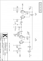
Here's something I found among my files based on what was originally an active RIAA correction.
The powerxformer states 250VAC but 230VAC should work as well.
The 5814A / 12AU7A CF can be replaced with something better.
I had a 12B4A in mind for that as it's a great tube and allows the use of 2 tubes per channel which in turn allows for optimimum channel separation.
A 7058 can be used instead of the 7025 (both are derivatives of the 12AX7A/ECC83) shown.
I didn't doublecheck the pinout for compatiblility.
Either way, low noise versions of the 12AX7 are recommended for a phonostage.
I didn't bother with direct coupling the AX7 to the CF as I really don't see the point of doing so in a BW limited cct in the first place and secondly it leaves more options in case a source other than phono needs to be fed through the preamp.
If someone sees a mistake, please don't hesitate to point it out.
I once built the version with the active RIAA which was pretty good given the "modest" cost.
Yet this circuit really shines with high quality components as far as anything behind the regulator is concerned.
If possible use handpicked caps for all RIAA components, the accuracy of the correction curve depends on it.
Cheers,
Attachments
Hi Frank,
thanks for the schematic, does the pot have to go between the cf and 7025?
In the schematic shown there is a 100k pot used, which still falls short of the 220k minimum load for the 7025. As I use a passive setup for the rest of my gear (mostly a tube buffered cdp, which has a low enough Zout to drive the passive pre), I really don't have the need to use the pot at this point, so could I just attach the cf to the cap behind the 7025, and use my passive setup after??
I also found this on the je labs page, which is very similar, although in this situation a passive 250k log pot was used instead of the cf.
http://members.myactv.net/~je2a3/JELsc-phonopre1.jpg
For the cf, if I need it I will use the tube you suggested.
In any case for either the power supply in your schematic seems excellent.
By the way Frank, can you recceommend somewhere in europe to get all the tubes for the circuit you mention, or the approx prices I should be paying, so that I can try to hunt them out here in the uk (last night I used the search engine on the web to look up 7025 prices, and I found an incredible variance in price)?
Many thanks for taking the time to help.
Raja
The 7025 is an EXACT replacement for the 12AX7. 7025s are extra low noise variants with spiral wound hum bucking filaments. The current production Sovtek 12AX7LPS is a 7025.
The 7058 is an automotive variant of the 'X7 that pins out like a 6922, including the internal shield. Sockets wired for "12" V. with pin 9 unconnected will work for both 'X7s and 7058s. Emission is supposed to be stable in a 7058 anywhere between 12 and 14 V. on the heater. That fact makes it very attractive for use with a 7812 regulator.
Kevin Deal at Upscale Audio (www.upscaleaudio.com) carries a late 1950s vintage MAZDA 'X7 that he claims is the quietest variety he's ever heard. Perhaps a pair of those tubes could be sourced in the EU at a more favorable price.
I believe that either an Octal 12SN7 or a Locktal 14N7 could be substituted for the 5814/12AU7 without component changes. The bigger socket offers improved channel separation.
IMO, regardless of topology, you should use Schottky diodes in the DC heater supply, as they have zero switching noise.
HI Eli,
I Eli, I'll look up those mazda valves you mention. For the heater supplies I have another option apart from the trusty 7812's, I have jung regulator pcb's which I can make up to the required voltage, thay can (i believe) handle the current demand, and are far less noisy than the (good) 7812's, and they work right down to dc, so it might an intersting substitue. For the valves I'll definatley stick with 7025's as logic tells that these are ideal in this type of application. The follower will be the one Frank suggested 12b4a.
Also is it wrong to use film caps after the regulator instead of the Black Gate's shown? I know Black Gate's are better than other caps, but in my experience poly caps outperform them in most applications. Obviously I won't be able to get film caps in 150uf sizes, but perhaps a couple of 40uf's or 80uf's in parrallel would suffice. Pricewise there's not much in it, as the Black Gate's are very expensive. My only concern is not to over tax the regulator by having such low impedence caps for them to drive.
Thanks
Raja
There's a fly in the ointment.
Raja,
Something you posted earlier in this thread went "click". You stated that you use a passive control center. I believe you will find the gain of the RCA circuit, as given, to be inadequate. It takes 54 dB. of gain to raise a "typical" MM cartridge's 4 mV. O/P to the 2 V. a CDP produces. IIRC, the RCA circuit is good for about 40 dB. That's not nearly enough.
Fortunately, some modifications, not affecting the RIAA network, should resolve the gain issue. Leave the 1st gain block and RIAA network untouched. The focus of the changes will be on the 2nd gain block. Switching from resistive loading to CCS loading will increase gain. The Bottlehead (www.bottlehead.com) C4S or an equivalent circuit will get the job done. Drive the CCS from the unregulated B+, as the CCS needs some voltage for proper operation and it also provides a good amount of PSR. To obtain max. gain, essentially the full mu of 100, the CCS loaded gain block should be DC coupled to the 12B4 cathode follower. A "textbook" operating point for the 'X7 is Ug = -2 V., Ia = 1.2 mA., and Ua = 250 V. That operating point is easily achieved by setting the CCS for 1.2 mA. and placing a red LED under the 'X7's cathode for bias.
A 7025's advantage is its hum bucking heater when AC heating is employed. Since you are going to use DC heating, select an 'X7 variety with a superior noise factor, like that late 1950s MAZDA.
Raja,
Something you posted earlier in this thread went "click". You stated that you use a passive control center. I believe you will find the gain of the RCA circuit, as given, to be inadequate. It takes 54 dB. of gain to raise a "typical" MM cartridge's 4 mV. O/P to the 2 V. a CDP produces. IIRC, the RCA circuit is good for about 40 dB. That's not nearly enough.
Fortunately, some modifications, not affecting the RIAA network, should resolve the gain issue. Leave the 1st gain block and RIAA network untouched. The focus of the changes will be on the 2nd gain block. Switching from resistive loading to CCS loading will increase gain. The Bottlehead (www.bottlehead.com) C4S or an equivalent circuit will get the job done. Drive the CCS from the unregulated B+, as the CCS needs some voltage for proper operation and it also provides a good amount of PSR. To obtain max. gain, essentially the full mu of 100, the CCS loaded gain block should be DC coupled to the 12B4 cathode follower. A "textbook" operating point for the 'X7 is Ug = -2 V., Ia = 1.2 mA., and Ua = 250 V. That operating point is easily achieved by setting the CCS for 1.2 mA. and placing a red LED under the 'X7's cathode for bias.A 7025's advantage is its hum bucking heater when AC heating is employed. Since you are going to use DC heating, select an 'X7 variety with a superior noise factor, like that late 1950s MAZDA.
Hi,
You're absolutely correct, the original drawing shows a 1M pot, not 100K...
That should teach me not to cut and paste drawings in the middle of the night.
You could do that.
Which brings me to Eli's remark regarding the gain:
I see two possibilities besides the CCS Eli suggests as a solution, either use an active RIAA correction as used in my design with the 300V B+ or use a gainstage a la SRPP instead of the CF.
Although the choice of tubes is admittedly rather limited for SRPP with a 250V B+, the SRPP has mu/2 gain, is pretty linear and has low enough Zout for the passive pre.
Unless it's in the 10K region perhaps....Is it?
They're really hard to come by nowadays....
Another interesting tube that's still available is the ex-USSR 6N2-P. Not sure if it's really low-noise though.
That won't be too easy...MAZDA was Philips-France and they had various types of ECC83s, not all of them are as LN as a good 7025.
Easier to score and good sounding is the NOS Tesla E83CC which is a copy of the TFK ECC803S.
Agreed 100%...I just don't know the type # by heart...
BTW, if anyone feels like doing the math on the 12B4A CF....I won't have much spare time for some weeks.
Cheers,
In the schematic shown there is a 100k pot used, which still falls short of the 220k minimum load for the 7025.
You're absolutely correct, the original drawing shows a 1M pot, not 100K...
That should teach me not to cut and paste drawings in the middle of the night.
I really don't have the need to use the pot at this point, so could I just attach the cf to the cap behind the 7025, and use my passive setup after??
You could do that.
Which brings me to Eli's remark regarding the gain:
I see two possibilities besides the CCS Eli suggests as a solution, either use an active RIAA correction as used in my design with the 300V B+ or use a gainstage a la SRPP instead of the CF.
Although the choice of tubes is admittedly rather limited for SRPP with a 250V B+, the SRPP has mu/2 gain, is pretty linear and has low enough Zout for the passive pre.
Unless it's in the 10K region perhaps....Is it?
What do you think of a 6EU7? It seems to be aimed at a low noise application.
They're really hard to come by nowadays....
Another interesting tube that's still available is the ex-USSR 6N2-P. Not sure if it's really low-noise though.
Perhaps a pair of those tubes could be sourced in the EU at a more favorable price.
That won't be too easy...MAZDA was Philips-France and they had various types of ECC83s, not all of them are as LN as a good 7025.
Easier to score and good sounding is the NOS Tesla E83CC which is a copy of the TFK ECC803S.
IMO, regardless of topology, you should use Schottky diodes in the DC heater supply, as they have zero switching noise.
Agreed 100%...I just don't know the type # by heart...
BTW, if anyone feels like doing the math on the 12B4A CF....I won't have much spare time for some weeks.
Cheers,

fdegrove said:
BTW, if anyone feels like doing the math on the 12B4A CF....I won't have much spare time for some weeks.
Cheers,
Hi,
Is there anyone here that can work out this for me please?
Thanks
Raja
Hi Frank,
I've decided it's probably better to get a bigger tranny or 2 and use those to build this circuit.
Do I need a 300-0-300 secondry?
So can I use the RCA circuit with it's passive riaa at 305v B+ and then use your (ultimate) buffer after?
If this is not possible I will build the ultimate pre with the active riaa stage.
With regards to the 1m attenuator, could I replace this with a 220k resistor in series with the signal, to give a fixed output? Although this may not be ideal, I can still use my passive pre for my cdp etc, and control the volume output of the phono/buffer with it???
So for really good performance, do I need one tranny per channel and also seperate trannies for the B+ to the buffer circuit????
Thanks
Raja
Hi,
You don't need a CT xfmr.
A 0-260VAC would do already, I used 2 per channel as each had a winding of 6.3VAC for the heaters of the EL86 and 12AX7A.
You'd still be facing the same gain (or lack thereof) problem with the passive RIAA.
You can leave the attenuator out, the 1M gridleak resistor of the 12BH7A WCF will take over it's role if you choose the active RIAA correction.
I used 2 per channel + a seperate one per channel for the 12V6 heater supply. You could use 1 per channel for the B+ but it's not the greatest solution.
Cheers,
Do I need a 300-0-300 secondry?
You don't need a CT xfmr.
A 0-260VAC would do already, I used 2 per channel as each had a winding of 6.3VAC for the heaters of the EL86 and 12AX7A.
So can I use the RCA circuit with it's passive riaa at 305v B+ and then use your (ultimate) buffer after?
You'd still be facing the same gain (or lack thereof) problem with the passive RIAA.
With regards to the 1m attenuator, could I replace this with a 220k resistor in series with the signal, to give a fixed output? Although this may not be ideal, I can still use my passive pre for my cdp etc, and control the volume output of the phono/buffer with it???
You can leave the attenuator out, the 1M gridleak resistor of the 12BH7A WCF will take over it's role if you choose the active RIAA correction.
So for really good performance, do I need one tranny per channel and also seperate trannies for the B+ to the buffer circuit????
I used 2 per channel + a seperate one per channel for the 12V6 heater supply. You could use 1 per channel for the B+ but it's not the greatest solution.
Cheers,
- Status
- This old topic is closed. If you want to reopen this topic, contact a moderator using the "Report Post" button.
- Home
- Amplifiers
- Tubes / Valves
- tube phono amp req'd