I have russian 6P41S (6Pi41C) tube and output transformer Visaton TR10.16 (1,2,4,8,16k primary and 4,8,16 ohm secondary; 10W). I would like to build a power amp with this tube and transformer. Any ideas?
6P41S datasheet is here: http://www.russiantubes.com/prop.php?t=12&p=273
6P41S datasheet is here: http://www.russiantubes.com/prop.php?t=12&p=273
Consider a SET circuit that borrows some of the DECWARE SE84's concepts. Set the O/P trafo up for an 8 KOhm primary. Triode strap the tube by connecting the screen grid to the plate via a 100 Ohm resistor. The high gm of the tube indicates that a control grid stopper resistor is needed.
A CLC filter following full wave rectified 120 VAC will give you a B+ rail that is comfortably within the 6p41s' specs. Without characteristic curves, a self bias arrangement will be DIFFICULT. Dennis Boyle's combination bias will solve the problem. Stand the cathode on an unbypassed 100 Ohm resistor. Use a bias supply to set the idle current for 13 W. total (plate + screen) dissipation.
The 5687, the 6GU7, and the 12BH7 appear to be reasonable candidates for the voltage gain/driver block. Cap. couple the driver to the "final". Choke or CCS loading the driver will perform better than resistive loading will, but resistive loading is satisfactory.
Eli Duttman said:Consider a SET circuit that borrows some of the DECWARE SE84's concepts. Set the O/P trafo up for an 8 KOhm primary. Triode strap the tube by connecting the screen grid to the plate via a 100 Ohm resistor. The high gm of the tube indicates that a control grid stopper resistor is needed.
A CLC filter following full wave rectified 120 VAC will give you a B+ rail that is comfortably within the 6p41s' specs. Without characteristic curves, a self bias arrangement will be DIFFICULT. Dennis Boyle's combination bias will solve the problem. Stand the cathode on an unbypassed 100 Ohm resistor. Use a bias supply to set the idle current for 13 W. total (plate + screen) dissipation.
The 5687, the 6GU7, and the 12BH7 appear to be reasonable candidates for the voltage gain/driver block. Cap. couple the driver to the "final". Choke or CCS loading the driver will perform better than resistive loading will, but resistive loading is satisfactory.
I did not understand it fully, but I'll try to
Could you draw or give links to some schematics that you are writing about?
Regardless of your mains voltage, you need a power transformer. A 220-0-220 V. secondary feeding a 5Y3 rectifier and a choke I/P (LCLC) filter should work out OK. 5Y3 equivalents of Russian manufacture are available.
A 6922 equivalent probably will work as a driver, but the mu is a tad high at 33. Don't bypass the cathode bias resistor. If the 6922 proves inadequate to the challenge of driving the Miller capacitance of the "final", use both sections of a 6922 in parallel. If you parallel sections, try to use tubes with closely matched sections.
A 6922 equivalent probably will work as a driver, but the mu is a tad high at 33. Don't bypass the cathode bias resistor. If the 6922 proves inadequate to the challenge of driving the Miller capacitance of the "final", use both sections of a 6922 in parallel. If you parallel sections, try to use tubes with closely matched sections.
Pentium100 said:
I did not understand it fully, but I'll try toI have mains voltage not 120VAC but 220VAC. But I thint that a voltage regulated power supply would be OK for this amp. Also, I have only USSR made tubes 6N23P (substitute for ECC88 or 6922). Woult it be good for driver stage?
Could you draw or give links to some schematics that you are writing about?
I mean no offfense but if you didn't understand what he said then you don't want to try to build a amp with a regulated supply as a project. Keep it simple at first. A 6N23P will be fine as a driver for a single ended circuit using a 6P41S. I'm going to guess you need a transformer with a 3K primary for the circuit. I would also highly recommend the Zen amp layout. I would need better data sheets to help out with the design. I couldn't find any that gave enough data for designing. Maybe someone else can help out? Do you have a particular rectifier tube in mind or are you planning on using SS rectifiers?
G said:
I mean no offfense but if you didn't understand what he said then you don't want to try to build a amp with a regulated supply as a project. Keep it simple at first. A 6N23P will be fine as a driver for a single ended circuit using a 6P41S. I'm going to guess you need a transformer with a 3K primary for the circuit. I would also highly recommend the Zen amp layout. I would need better data sheets to help out with the design. I couldn't find any that gave enough data for designing. Maybe someone else can help out? Do you have a particular rectifier tube in mind or are you planning on using SS rectifiers?
I have built a phono preamp with regulated power supply (320V to 150V with MOSFET). I am planning to use solid state diodes for rectifying because I don't know which USSR made tubes is fectifiers and it is hard to find vacuum tubes where I live. But on the other hand, tubes are relatively cheap (6N23P costs abuot $3). I didn't understand him because I am not very good at English terminology. A grid stopper resistor is a resistor that is conncted between amp input and the tube's grid or the resistor that is connected between tubes grid and GND?
And what is the Zen amp layout? If I have a transformer with 2K and 4K primary, which primary is better to use?
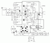
Try this schematic!
I have built this amp.
The only thing I added was 2 -470K 2W between the phase inverters grids to ground.
Also I eliminated the feedback loop (too much oscillation you can experiment with if you want to.)
http://www.audiofanatic.it/Schemi/Tipo/Valvole/finali/pic_finali_PP/6P41S_PP.jpg
I have built this amp.
The only thing I added was 2 -470K 2W between the phase inverters grids to ground.
Also I eliminated the feedback loop (too much oscillation you can experiment with if you want to.)
http://www.audiofanatic.it/Schemi/Tipo/Valvole/finali/pic_finali_PP/6P41S_PP.jpg
I have russian 6P41S (6Pi41C) tube and output transformer Visaton TR10.16 (1,2,4,8,16k primary and 4,8,16 ohm secondary; 10W). I would like to build a power amp with this tube and transformer. Any ideas?
6P41S datasheet is here: http://www.russiantubes.com/prop.php?t=12&p=273
Bump...
There is a short thread at :
http://www.diyaudio.com/forums/tubes-valves/171034-home-grown-tube-amps.html
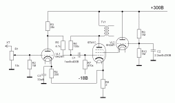
"The meter is on the plates of the output tubes.
The B+ is 315 VDC
At full output the plate ma is 80ma for both tubes.
I am using fixed bias with a 500 ohm 25 watt resistor
The bias on the control grids is -47 VDC.
with a by-pass cap of 47 mfd. 250 VDC.
...
Here is the basic schematic (This schematic does not work!!! I had to tweak it to get it to work.)"
With 510R in the cathode and -47V grid to cathode, there would be 92ma of cathode current. Since it is stated that there is 80mA for both tubes I suspect it is a typo and there is -20.5V g2-k.
Looking at the plate graph on sheet 5 in the DJVU:
Ðàäèîëàìïà 6Ï41Ñ
This is off by 30%, but may be correct.
More to point, the graph is at 170V g2, and the schematic shows g2 either at anode(triode mode) or UL. In UL it is at near 315V which should put cathode current much higher. Unfortunatly it is stated that the schematic is wrong.
Why to care?
I'm trying to test 6P41S on my curve tracer, and I believe it may be drawing g2 Current in what is supposed to be the off state (g1 at -30V).
Again looking at the graph on page 5 of the DJVU file, if the tube draws 70mA of anode current at g1 = -20V, g2=170, and a=250, then it appears that -30V might be insufficient to bias the tube off, and I can not test it in my test set as it only supports grid voltage to -30V. The curvetracer applies half rectivied B+ to the anode at all times, and the g2 supply is always applied as well.
When I tried to test a tube, it pulsated along with the plate sweeps, and I suspect g2 was glowing. My g2 supply is current limited to 50mA, and as the test runs, the g2 voltage drops which I am intrepreting to be g2 conduction.
Can anyone confirm this?
Last edited:
Visaton TR10.16 is a 100v line transformer, NOT a SE output transformer.
You may be able to use it as a Push-pull transformer see following link;
Cheap Output Transformers
You may be able to use it as a Push-pull transformer see following link;
Cheap Output Transformers
- Status
- This old topic is closed. If you want to reopen this topic, contact a moderator using the "Report Post" button.
- Home
- Amplifiers
- Tubes / Valves
- Ideas for SE amp with this tube

