Hi all
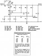
I built the showed regulated PS using ECL82 and two 62V zener diodes stacked aiming for 300VDC. I'm getting about 70VDC out of it.
I measured 20volts between pin 8 and GND. I assume this must be the problem (shoulf read 124V). With the 100k potentiometer I can adjust the output between 60 and 80VDC, exactly 1/4 of the range recommended for 120V of zener (240 till 320VDC).
I connected two 1k2 resistors to the "heater bias", each one going to one of the fillaments.
Have you got any opinions what van be wrong here?
Attachments
continuation
After solving the problem with the ECL82 regulator I want to try this one http://www.the-planet.org/6GV8.html
The schematic is almost the same, so if ECL82 regulator turns out right, ECL85 must also turn out right. The ECL85 is cheaper and more available at my place. Problem is that it outputs 250VDC while I need 300VDC.
Shall it be possible to lift the zener voltage reference somewhat (let's say ~150V), substitute R5 and R3 for 100k and put a 100k potentiometer whit it's wiper connected to R4?
Maximum ratings for ECL85 plate voltages are 250VDC...so.
Hi,
That alone won't do, you'll just lose all the regulation.
First of all, if you want to output 50 more volts, you'll have to input at least 50 more too.
The Zener or VR tube is just a reference voltage often chosen for it's current range in the case of the VR tubes. Voltage rating is really only secondary to that.
IOW, swapping say, a OA2 for a OG3 is probably going to give you only a few volts more on the output of the regulator.
Everything else will need adjustment too.
As for the ECL85, if you go beyond the heater to cathode isolation voltage you'll need to bias the heater upwards.
Anode to cathode voltage is really well into the 500V range so that's not a problem since the tube is floating between input and output.
Cheers,")
Shall it be possible to lift the zener voltage reference somewhat (let's say ~150V), substitute R5 and R3 for 100k and put a 100k potentiometer whit it's wiper connected to R4?
That alone won't do, you'll just lose all the regulation.
First of all, if you want to output 50 more volts, you'll have to input at least 50 more too.
The Zener or VR tube is just a reference voltage often chosen for it's current range in the case of the VR tubes. Voltage rating is really only secondary to that.
IOW, swapping say, a OA2 for a OG3 is probably going to give you only a few volts more on the output of the regulator.
Everything else will need adjustment too.
As for the ECL85, if you go beyond the heater to cathode isolation voltage you'll need to bias the heater upwards.
Anode to cathode voltage is really well into the 500V range so that's not a problem since the tube is floating between input and output.
Cheers,
Hi,
If you want to increase output voltage you need to either increase R5 or decrease R3, the circuit is trying to keep the voltage at the connection point between R3 and R5 a few volts below the voltage at the cathode of the triode, i.e. the voltage of the Zener diodes 137V so maybe this voltage is ~130V. If R3 and R5 are equal the output voltage will be ~2x 130V or 260V.
For improved performance I would use a VR tube instead of Zener diodes, high voltage Zeners have bad regulation, VR tubes are better. If you use a 150V VR tube like 0A2 with R3 140kohm, R5 150kohm the output voltage will be close to 300V. If you select to still use zeners I would increase C4 to at least 47uF to reduce Zener noise and reduce R7 to 33k to ensure that enough current is drawn trough the zeners, this also reduce noise and improve regulation.
Regards Hans
Thanks for the reply's.
I would also rather use VR tubes instead of zener's, but, there's not much logic in the brazilian prices of tubes. While a ECL85 costs 1/2 euro, the cheapest 85A2 I found costs 10 euro.
I found those cheap ECL85 and others tubes from various shops who sell/sold TV tubes, but neither of them have VR tubes. Didn't they use VR tubes in TV's?
I will keep searching.
Hi,
Happened to me too when I was snooping around Santa Ifigenia, while the ECL85 is probably not in demand at all the VR tubes and thyratrons are still used by the industry in bresil. Hence the higher price.
Do you mind checking how it responds to variations of the load?
Cheers,
While a ECL85 costs 1/2 euro, the cheapest 85A2 I found costs 10 euro.
Happened to me too when I was snooping around Santa Ifigenia, while the ECL85 is probably not in demand at all the VR tubes and thyratrons are still used by the industry in bresil. Hence the higher price.
Drawing 20mA of it decreases output in 3~4VDC.
Do you mind checking how it responds to variations of the load?
Cheers,
Do you mind checking how it responds to variations of the load?
Hi Frank. I will check this out. I'm also curious "how well" the ECL85 is regulating.
Happened to me too when I was snooping around Santa Ifigenia, while the ECL85 is probably not in demand at all the VR tubes and thyratrons are still used by the industry in bresil. Hence the higher price.
About brazilian tube shops. Rei das Válvulas, in Rio, had some low priced VR tubes. A month ago I asked a new quotation and their prices rised 3 or even 4 times. Rei do som in São Paulo is asking 16 euro for a 6EM7, while I can buy them at the shop around the corner for 1 euro.
ECL85 built
Hi Frank
I built the ECL85 regulator, 2x. I have done some measurements and calculations at one of them. With a 220k load it put a 300VDC out, drawing 20mA of it fell to 287VDC. That means a 750R output impedance, not that nice.
The second regulator I built seems to be much better, showing no voltage drop while a resistor pulls out some current. Really weird... Well, I will do some further measuremens this evening.
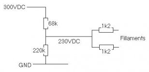
Second point. The specified maximum heater - cathode voltage for the ECL85 is 100V, for both triode and pentode. The triode cathode is at ~155V and the pentode cathode at ~300V. mean value is ~ 225V. To bias the heaters I´m using 68k and 220k in series, as shown at the picture. Is this good? I ask because you don´t say anything about biasing heaters at your 250VDC regulator using ECL85 and 85A2.
Hi Frank
I built the ECL85 regulator, 2x. I have done some measurements and calculations at one of them. With a 220k load it put a 300VDC out, drawing 20mA of it fell to 287VDC. That means a 750R output impedance, not that nice.
The second regulator I built seems to be much better, showing no voltage drop while a resistor pulls out some current. Really weird... Well, I will do some further measuremens this evening.
Second point. The specified maximum heater - cathode voltage for the ECL85 is 100V, for both triode and pentode. The triode cathode is at ~155V and the pentode cathode at ~300V. mean value is ~ 225V. To bias the heaters I´m using 68k and 220k in series, as shown at the picture. Is this good? I ask because you don´t say anything about biasing heaters at your 250VDC regulator using ECL85 and 85A2.
Attachments
Hi,
Erik,
The reason I didn't mention biasing the heaters with respect to the cathode is simply that it should work fine even without it in this application.
In your regulator you're close to the limit but still safe and since you're using bias anyway you'd be O.K. even with a dodgy ECL85 in this respect.
Vkf for both triode and penthode is 200V, the voltages you measure won't do any damage as most are derived from the feedback loop and the penthode is basically "floating" much in the same way semiconductors are in similar HV applications where they're used as series pass elements.
Cheers,
Erik,
Is this good? I ask because you don´t say anything about biasing heaters at your 250VDC regulator using ECL85 and 85A2.
The reason I didn't mention biasing the heaters with respect to the cathode is simply that it should work fine even without it in this application.
In your regulator you're close to the limit but still safe and since you're using bias anyway you'd be O.K. even with a dodgy ECL85 in this respect.
Vkf for both triode and penthode is 200V, the voltages you measure won't do any damage as most are derived from the feedback loop and the penthode is basically "floating" much in the same way semiconductors are in similar HV applications where they're used as series pass elements.
Cheers,
VR tube spice model
HI,
I'm considering building a (not so) similar power supply for use with a 811-3 amp. The design uses a couple of voltage reference tubes and has a B+ of 800V.
However, I have this silly idea that I must thouroughly simulate everything in spice before I even order the parts. The problem is I can't find a spice model for a gas tube anywhere, so I'm considering switching to zeners ... Any ideas ?
HI,
I'm considering building a (not so) similar power supply for use with a 811-3 amp. The design uses a couple of voltage reference tubes and has a B+ of 800V.
However, I have this silly idea that I must thouroughly simulate everything in spice before I even order the parts. The problem is I can't find a spice model for a gas tube anywhere, so I'm considering switching to zeners
... Any ideas ?Hi Paracelsus,
Why dont you make a model of a VR tube using a Zener model. Most data sheets for VR tubes have information of regulation which would give you dynamic resistance. For capacitance I think you need to guess but it should not be so difficult. When you make the model of the VR tube you will find that dynamic resitance is much less than for a Zener of similar voltage and if you measure noise you will find that also noise is much less in the VR tube.
I work a bit different from you, I calculate all by hand first, then I usually build the circuit and measure it to find out if it behave as it should, after that I model the circuit in Spice and have a hard time adjusting the individual models so they fit reality, I have found that especially tube models usually are very bad and all the models I use I have modified after measuring on real circuits. Sometimes I also do some initial modeling in Spice to test some crazy idea but if i am going to build something I usually calculate it trough by hand before building it in order to avoid any problems.
Maybe I should also mention that I enjoy the kind of math that is involved when designing tube amps. I would probably use Spice more if I could get better tube models and/or if I was doing commercial design but even then I would do manual calculation for sanity checks.
Regards Hans
Dear ErikDeBestHi all
I built the showed regulated PS using ECL82 and two 62V zener diodes stacked aiming for 300VDC. I'm getting about 70VDC out of it.
I measured 20volts between pin 8 and GND. I assume this must be the problem (shoulf read 124V). With the 100k potentiometer I can adjust the output between 60 and 80VDC, exactly 1/4 of the range recommended for 120V of zener (240 till 320VDC).
I connected two 1k2 resistors to the "heater bias", each one going to one of the fillaments.
Have you got any opinions what van be wrong here?
I am writing to you as I myself built the same regulator. I aqm having the same problem you had with output voltages. I got 50 to 60 Volts at the output of the regulator. I wonder if you may share the solution to this problem. I checked and re cheked all connections and proper values of resistors etc. All attempts have been unlucky so far. Kind rgrds. Stefifiun (Italy)
- Status
- This old topic is closed. If you want to reopen this topic, contact a moderator using the "Report Post" button.
- Home
- Amplifiers
- Tubes / Valves
- regulated PS - with Zener diode