Hello,
In early May I asked questions at this forum in regard to my Pentron tube open reel stereo Hi-Fi system. "WHAT TYPE OF PART IS THIS?"
I hope to upgrade the electronics inside to make it sound better just for the fun of it.
After clearing some things off my desk I now have time to work on this project.
Here is my problem I know how to remove and replace all of the capacitors and resistors but am absolutely lost when it comes to selenium rectifiers.
You guys have been of great help so far. I have the recommended 1N4007s on hand and am ready to start.
However, how is the proper way to replace the selenium rectifier with these?
I diagram that was provided by planet10 in the "WHAT TYPE OF PART IS THIS?" thread was helpful and I think I understand it but want to make sure I got it right.
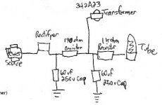
Here is a rough diagram showing the current circuit layout including the selenium rectifier.
This drawing of mine shows just the stuff going from the power supply > the selenium rectifier > to the tube.
In early May I asked questions at this forum in regard to my Pentron tube open reel stereo Hi-Fi system. "WHAT TYPE OF PART IS THIS?"
I hope to upgrade the electronics inside to make it sound better just for the fun of it.
After clearing some things off my desk I now have time to work on this project.
Here is my problem I know how to remove and replace all of the capacitors and resistors but am absolutely lost when it comes to selenium rectifiers.
You guys have been of great help so far. I have the recommended 1N4007s on hand and am ready to start.
However, how is the proper way to replace the selenium rectifier with these?
I diagram that was provided by planet10 in the "WHAT TYPE OF PART IS THIS?" thread was helpful and I think I understand it but want to make sure I got it right.
Here is a rough diagram showing the current circuit layout including the selenium rectifier.
This drawing of mine shows just the stuff going from the power supply > the selenium rectifier > to the tube.
Attachments
My understanding on how to do this
Here is my understanding on how these are to be soldered in place of the selenium rectifier.
Remove the selenium rectifier.
Solder in its place one diode with the cathode in one direction and another with the cathode in the other.
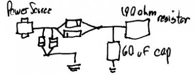
At the power source end I solder one diode with the cathode in one direction and another with the cathode in the other. The opposite ends of each solder to ground.
Is this correct?
I drew up the below attached diagram for clairification.
Here is my understanding on how these are to be soldered in place of the selenium rectifier.
Remove the selenium rectifier.
Solder in its place one diode with the cathode in one direction and another with the cathode in the other.
At the power source end I solder one diode with the cathode in one direction and another with the cathode in the other. The opposite ends of each solder to ground.
Is this correct?
I drew up the below attached diagram for clairification.
Attachments
One side of the selenium rectifier will be marked with a plus (+). The new rectifier will replace the old one, but the striped end goes to where the + end of the selenium was. By process of elimination, the unstriped end goes to where the other selenium rectifier lead was. The selenium rectifier should be discarded.
Edit: I'm not sure I understand your drawings.
Edit: I'm not sure I understand your drawings.
Hello,SY said:One side of the selenium rectifier will be marked with a plus (+). The new rectifier will replace the old one, but the striped end goes to where the + end of the selenium was. By process of elimination, the unstriped end goes to where the other selenium rectifier lead was. The selenium rectifier should be discarded.
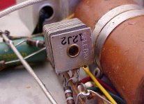
Here is the problem. There isn't a "+" on the old recitifier. Attached is a close up.
The diagram provided to me in the afore mentioned thread suggests that I use four 1N4007s to create a "half wave" recitifer as a replacement.
[ QUOTE] Edit: I'm not sure I understand your drawings. [/QUOTE]
I can do a better one if need be. the schematic was something I quicly scribbled down.
Attachments
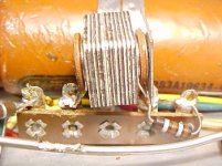
here attached is a close up of the recitifer showing the end that factes the tube side of the circuit.
I just looked it over and this is the side of the "+." Barely noticable in the scans, however.
How would I solder in the 4 diodes to replace it?
I just looked it over and this is the side of the "+." Barely noticable in the scans, however.
How would I solder in the 4 diodes to replace it?
Attachments
darren01 said:
How would I solder in the 4 diodes to replace it?
BTW, the metalic bar shown immeditely to the left of the recitifier in that attachment is the ground terminal.
It looks from your photo like it's just a two terminal device, i.e., a half-wave rectifier. So all you need is one of the silicon diodes to replace it. The earlier discussion with planet 10 involved using 4 diodes for a redesign/rebuild of that supply. You can do that, but given where you are at the moment, I'd just do the one-for-one swap, get the thing working, and save the other 3 diodes for when you're ready to take the next step to a full-wave bridge.
Make sure you replace the electrolytic capacitors, too; they tend to go pretty leaky with age.
Make sure you replace the electrolytic capacitors, too; they tend to go pretty leaky with age.
What would a full wave bridge do to improve the sonics of the unit over a half wave?
Check.
Thanks for the advice. You just made the project much more easier for me to figure out.")
BTW, What would a full wave bridge do to improve the sonics of the unit over a half wave?
That is the next step. A couple of the capacitors in this unit are 60uf. I checked and they don't make them like that any more. I can get several different ones to get it near 60uf but would rather use jsut one.
However, that is a topic for another thread.
Darren
SY said:It looks from your photo like it's just a two terminal device, i.e., a half-wave rectifier. So all you need is one of the silicon diodes to replace it. The earlier discussion with planet 10 involved using 4 diodes for a redesign/rebuild of that supply. You can do that, but given where you are at the moment, I'd just do the one-for-one swap, get the thing working, and save the other 3 diodes for when you're ready to take the next step to a full-wave bridge.
Check.
Thanks for the advice. You just made the project much more easier for me to figure out.
BTW, What would a full wave bridge do to improve the sonics of the unit over a half wave?
Make sure you replace the electrolytic capacitors, too; they tend to go pretty leaky with age.
That is the next step. A couple of the capacitors in this unit are 60uf. I checked and they don't make them like that any more. I can get several different ones to get it near 60uf but would rather use jsut one.
However, that is a topic for another thread.
Darren
In theory, the full-wave bridge will give you a bit better noise performance, with respect to hum. Less ripple. Regulation is better, too, but that's really not an issue in this application where you're dealing with (presumably) all class-A audio circuits.
Good luck with this repair. Please let us know how it works out!
Good luck with this repair. Please let us know how it works out!
Higher Voltages
Hi Darren,
Modern rectifiers have less voltage drop and internal resistance than the Selenium rectifier that you have. You may have to add a series resistor to lower the voltage to normal levels. I would expect the voltages to be 10 -20 % high without a dropping resistor. Trial and error is best here. Can you get a schematic with voltage readings?
-Chris
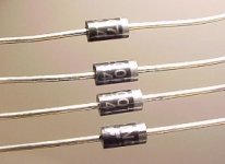
I just pulled a larger one of these diodes out of a portable... rather intriuging device really, big heatsink and all
Too bad it's so simple.
My point being I didn't find this one dead or leaky and there was also only one in this circuit. so yeah half-wave all the way baby..
It really gives that 1930's Goth-tech feel
Too bad it's so simple.
My point being I didn't find this one dead or leaky and there was also only one in this circuit. so yeah half-wave all the way baby..
It really gives that 1930's Goth-tech feel
dhaen said:Apart from higher voltage out, a silicon replacement will cause a much higher ripple current in the reservoir (first smoothing) cap, that will make it go bang.
When fitting a silicon replacement we always used a series resistor.
What kind of resistor?
Series resistor
Hi Darren,
It depends on how much current you are drawing. The unit you had looks like the HV rectifier, so low current. Try a 1K and go from there. When the old one failed, it had a high resistance over a new one of the same type. If you can find a schematic, use a resistance that sets the High voltage in the nominal range. What is the unit you are working on?
-Chris
Re: Series resistor
Hello,
I just checked the voltage on both sides of the recitifier.
The voltage from the transformer to the "-" of the recitifier is 213V.
From the "+" of the recitifier to the first capacitor the voltage is 16.8 mV.
What resistor should I use?
The model that I am working on is the Pentron Triumph XP-60s.
There are two dealers online that are selling a repair manual but I'd rather not spend the $20+ because I only paid $10 for the unit.
I cannot find a free scematic for it online, either.
BTW, the electrolytic are 60-60/40/25 mf capacitor with voltage values at 250-250/200/25
Darren
Hello,
I just checked the voltage on both sides of the recitifier.
The voltage from the transformer to the "-" of the recitifier is 213V.
From the "+" of the recitifier to the first capacitor the voltage is 16.8 mV.
What resistor should I use?
anatech said:If you can find a schematic, use a resistance that sets the High voltage in the nominal range. What is the unit you are working on?
-Chris
The model that I am working on is the Pentron Triumph XP-60s.
There are two dealers online that are selling a repair manual but I'd rather not spend the $20+ because I only paid $10 for the unit.
I cannot find a free scematic for it online, either.
BTW, the electrolytic are 60-60/40/25 mf capacitor with voltage values at 250-250/200/25
Darren
- Status
- This old topic is closed. If you want to reopen this topic, contact a moderator using the "Report Post" button.
- Home
- Amplifiers
- Tubes / Valves
- How do I replace this 40+ year old selenium rectifier?