Spec sheets look interesting, Eli. Do you know where these diodes can be purchased?
Tube Builder (www.tubebuilder.com) carries the SiC Schottkys.
The 1200 PIV parts are costly, but the 1 A./600 PIV parts are under 2 USD each. You can build a bridge rectifier with UF4007s in the ground legs and SiC Schottkys in the B+ legs that will be very quiet, as the Schottkys block the PN reverse recovery spike. IMO, containing costs while retaining performance can't be bad.
SE813 AMPLIFIER SHEMATIC
HERE THE SHEMATIC OF 813 TUBE AMPLIFIER.
http://homepages.ihug.co.nz/~rwillis/alex/
HERE THE SHEMATIC OF 813 TUBE AMPLIFIER.
http://homepages.ihug.co.nz/~rwillis/alex/
if you have to regulate
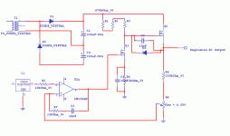
this is a close approximation of the Horowitz and Hill HV regulated supply with a voltage doubler. i have used this supply for a HV lab supply -- instead of a reference I use a DAC, etc., etc.
you might have to adjust the compensation values for your particular situation.
the bottom of C3 should be grounded.
Attachments
Re: power supply
Take a look at the parametric search engines at International Rectifier or Fairchild Semiconductor -- Fairchild, in particular, should have out their 1200 Volt Super MOSFET. (They talked about it on one of their web-seminars recently.)
The supply I have built only goes to ~400 volts, I am using IRFPG40's.
noyan said:OK. What is Q2 ?
Take a look at the parametric search engines at International Rectifier or Fairchild Semiconductor -- Fairchild, in particular, should have out their 1200 Volt Super MOSFET. (They talked about it on one of their web-seminars recently.)
The supply I have built only goes to ~400 volts, I am using IRFPG40's.
Look at the voltage doubler power suppy at`s used in my 805 SET at Dave (planet10) so kindly posted for me, it works well as is simple.
http://www.diyaudio.com/forums/showthread.php?s=&threadid=33992
Cheers George
http://www.diyaudio.com/forums/showthread.php?s=&threadid=33992
Cheers George
Re: IXTP3N120 1200V/3A SUPER MOSFET
The circuit I have shown would also require that the values of the caps in the doubler be capable of handling more than 450V for 900V out -- thus you would use a pair in series -- i.e. 680uF/350VDC.
The Ixys transistors are available from Digikey (if anyone is wondering) they are $6.09 ea.
noyan said:If i use: IXTP3N120 1200volts / 3A high voltage super mofset in my shematic and remove IRF740 and BUX48. Then, 900 volts will not be a big deal for such strong mosfet. ???
The circuit I have shown would also require that the values of the caps in the doubler be capable of handling more than 450V for 900V out -- thus you would use a pair in series -- i.e. 680uF/350VDC.
The Ixys transistors are available from Digikey (if anyone is wondering) they are $6.09 ea.
i was just wondering... i had a look at george's power suply, and saw the two diodes in series on it, and it made me think how many times i have seen this used... so maybe i'm getting a little off topic, but what is the advantage of putting two diodes in series? is this to do with the switching noise or something??? anyone on this post know?
cheers
cheers
You series diodes (with voltage equalizing resistors across them) to form a diode with a higher working voltage. For example, two 1000V diodes in series would form the equivalent of a 2000 volt diode. The only difference between that composite diode and a "genuine" 2000V diode is that the composite will have two times the voltage drop, i.e., 1.4V rather than 0.7V.
Hi,
Due to that they are a little better at surviving inrush current surges and yes, the spikes are a little less pronounced than on a single diode too.
In the circuit as shown by George they're used in a voltage doubler so the 1N4004 being a 400V 1A device wouldn't have a chance when left on its own there, hence the 2 diodes in series making it essentially a 800 Fv device at 1A and 800V PIV but with a Fvd of 1.4V iso 0.7V as SY has pointed out.
Cheers,
two times the voltage drop, i.e., 1.4V rather than 0.7V.
Due to that they are a little better at surviving inrush current surges and yes, the spikes are a little less pronounced than on a single diode too.
In the circuit as shown by George they're used in a voltage doubler so the 1N4004 being a 400V 1A device wouldn't have a chance when left on its own there, hence the 2 diodes in series making it essentially a 800 Fv device at 1A and 800V PIV but with a Fvd of 1.4V iso 0.7V as SY has pointed out.
Cheers,
- Status
- This old topic is closed. If you want to reopen this topic, contact a moderator using the "Report Post" button.
- Home
- Amplifiers
- Tubes / Valves
- 900v. 100ma. Power supply for 813 tube amplifier
