I need to make a power supply unit for my new project. I will build a 813 SE Ultralinear amplifier. It needs 900v, 100ma. I attached this shematic suitable for up to 450v. How can i revise it up to 1000v ? Can you offer me which Fet and transistor can be use for this reason? Noyan
Attachments
I'm afraid you can't just scale a circuit up from 280V to 900V. There are a great deal more safety issues with 900V, and frankly, if you don't know about them, you shouldn't be considering building an amplifier using a 900V supply. With 900V you only have to be unlucky once...
900V i like to deal with difficult things!
Thank you very much for your reply! I am understaning your concern very well. I am affraid to work with 900v too. This high voltage is very dangerious But, this shematic is working very well and there is no hum. No need any expensive and big choke transformer. If i use bux98 transistor in this circuit than i can get safely 450v. I can build two of them and serial it makes me 900volts. Is it meanful or not for you?
Thank you very much for your reply! I am understaning your concern very well. I am affraid to work with 900v too. This high voltage is very dangerious But, this shematic is working very well and there is no hum. No need any expensive and big choke transformer. If i use bux98 transistor in this circuit than i can get safely 450v. I can build two of them and serial it makes me 900volts. Is it meanful or not for you?
noyan said:I need to make a power supply unit for my new project. I will build a 813 SE Ultralinear amplifier. It needs 900v, 100ma. I attached this shematic suitable for up to 450v. How can i revise it up to 1000v ? Can you offer me which Fet and transistor can be use for this reason? Noyan
Hello ,
900V , 100mA ? I would use valve rectifiers such as the filamentary U19 and dampers like the EY500A/PY500A/6D22S , which offer a slow start . Both of these can be used with CLC supples . Choke input supplies for 900V are a little , well , scary !
cheers
316a
")
I think there is an 813 SE schematic available online that employs a regulated supply. Microprocessor controlled PSU, if I remember it right.
Search and thou shalt find.
In my 813 amp I´ll use tube rectifiers and chokes, partly because I don´t want to mess with 900V regulators.
Assembling the Mosfet on the heatsink (which I assume is necessary) with proper insulation will be an issue for you.
Search and thou shalt find.
In my 813 amp I´ll use tube rectifiers and chokes, partly because I don´t want to mess with 900V regulators.
Assembling the Mosfet on the heatsink (which I assume is necessary) with proper insulation will be an issue for you.
90 watts isn't a lot to control -- I would recommend that you voltage regulate the PRIMARY of the HV transformer -- you can do this in a variety of ways -- i.e. with an amplifier driven by a sine wave generator (don't forget the automatic gain control, and don't forget to use an opto-isolator in the feedback loop.)
you can probably pump up the frequency of the sine oscillator to a few hundred hertz with an ordinary transformer. this allows smaller filtering capacitors on the output.
when dealing with high voltages you must make sure that the transformer is rated for its purpose -- don't do something like doubling the primary voltage of a 400VCT with a back to back transformer (110:12.6::6.3:220) -- the insulation will break down. Fair Radio Sales in Lima OH has HV transformers.
also -- the wiring in the power supply must be rated for about 15% more than the voltage you seek to derive --
I'm not going to use regulated HV in my triode strapped 813 SE. I already have transformers with 685V AC with a 655V AC tap and intend to use a bridge rectifier with 1N4007, 3 in series in each leg with snubbers. This will feed a CLC filter with a rather low value of the first C.
The bias supply will also be unregulated so mains variations will not move the operating point around too much.
The bias supply will also be unregulated so mains variations will not move the operating point around too much.
900v. big trouble!
Yes, i know that shematic but micropresessor controlled power supply unit is too complex. This shematic is impressed me because it has no hum and so simple to do. Please see spec of BUX98A. 900v voltage is so high but ONLY 90 watt for per channel, BUX98A is looking suitable for this use. Any comments? If you say again no, than i am offering to use two main transformers and make two unit of this circuit. I will have 2 times let's say 450 volts. When i connect them together in serial i will have 900v. is it not wright? Where i am making mistake?
Thanks all
Jax,
1N4007s are very noisy. UF4007s are inexpensive and MUCH easier to "snub" than 1N4007s are.
With a PIV of 1000, 2X '4007s in each leg of the bridge should be adequate. Voltage equalizing resistors are an "anal retentive" touch.
Have you considered a hybrid bridge with SS diodes forming the ground connection and vacuum damper diodes forming the B+ connection? The forward voltage drop in vacuum dampers is relatively low. No snubber is needed, as the vacuum diodes block the reverse recovery spike. The B+ rise is SLOW; so, no worries about cathode stripping. IMO, the hybrid bridge is very attractive.
hi,
i love that idea eli about the hybrid bridge rectifier.... i already plan to use it in my next project! thanks for that one!
by the way, i was curious... what's the advantage of using an ultra fast version over the standard version of a diode??? you mention more noise... how does this come about? thanks for your help.
when it cones to SS electronics, i have no idea, and i never really spend the time to get an idea, even though i should
so therefore, i have no idea what the ratings on those FET's and Transistors as i have none of the data sheets, and don't know where to source them.. that would mean i'd have to spend time searching... but anyway... you could try a voltage doubler idea in place of a bridge rectifier... if you do this, make sure you use a full wave version, as half wave will leave you with more ripple on the PS then what you get with full wave.
cheers
Here is a transformer that would turn the trick for you:
http://cgi.ebay.com/ws/eBayISAPI.dll?ViewItem&category=3284&item=3025322003
900 VDC is a scary thing. Are you sure you want to build that monster? Also hammond makes a 700 series HV plate transformers that will supply that type of power. Not sure about chokes though. If the amp doesn't work out you will still have a damn nice welding rig.
if you want a cheap as HV tranny, why not get an old microwave oven tranny, and rewind to suit??? these things can handle like at least 1000W normally, and have about a 2kV secondary... so they're monsters.
about working with very high voltages... while working with 900V there is of course a big potential danger (pun intended), but as long as propper care with both construction and layout is taken, you sould be safe... but for gods sake, be VERY CAREFUL. take all propper safety precautions when building, and remember that when working with something like this, it pays to be paranoid... especially when probing the live amp... i would suggest clipping BOTH of your meter probes on while the amp is OFF for every measurement you take, and keep hands well out of chassis while it's on... while there's not a potential for big arcs at this voltage, there is definately potential for arcing... so another thing to do would be make sure everything inside the amp is well away form any of the metal used that's either conected or is part of the external chassis... and use pots with plastic shafts on them... and another good thing i suggest once you know everything's working... paint all open leads/joins whatever with liquid electrical tape... this is another paranoid move that might just pay off oneday... and of course there are plenty other points to remember, but that's what i've got to say for now...
by the way G, just for future reference, you stated:
just remember when refering to power, we are refering to P = VI in this case (it's a slightly different equation for AC, but this is DC here)... this amp is only 900V and 100mA, so P = 900 x 0.1 = 90W... not a lot of power... just thought i'd point that out... probably just a mistake you made, but if it was what you thought, then hope i helped you out.
cheers
about working with very high voltages... while working with 900V there is of course a big potential danger (pun intended), but as long as propper care with both construction and layout is taken, you sould be safe... but for gods sake, be VERY CAREFUL. take all propper safety precautions when building, and remember that when working with something like this, it pays to be paranoid... especially when probing the live amp... i would suggest clipping BOTH of your meter probes on while the amp is OFF for every measurement you take, and keep hands well out of chassis while it's on... while there's not a potential for big arcs at this voltage, there is definately potential for arcing... so another thing to do would be make sure everything inside the amp is well away form any of the metal used that's either conected or is part of the external chassis... and use pots with plastic shafts on them... and another good thing i suggest once you know everything's working... paint all open leads/joins whatever with liquid electrical tape... this is another paranoid move that might just pay off oneday... and of course there are plenty other points to remember, but that's what i've got to say for now...
by the way G, just for future reference, you stated:
Also hammond makes a 700 series HV plate transformers that will supply that type of power.
just remember when refering to power, we are refering to P = VI in this case (it's a slightly different equation for AC, but this is DC here)... this amp is only 900V and 100mA, so P = 900 x 0.1 = 90W... not a lot of power... just thought i'd point that out... probably just a mistake you made, but if it was what you thought, then hope i helped you out.
cheers
by the way, i was curious... what's the advantage of using an ultra fast version over the standard version of a diode??? you mention more noise... how does this come about? thanks for your help.
ALL PN diodes exhibit switching noise called a reverse recovery spike. The spike of the UF varieties is of shorter duration; so, there is less noise. The late John ("Buddha") Camille devised a reverse recovery spike filter (RRSF) for use with the UF4007 that reduces its noise levels to those of vacuum diodes. Without "snubbing" of some kind, FREDs are the least noisy PN devices.
The "recent" introduction of high PIV Silicon Carbide (SiC) Schottky diodes by Cree is a milestone in SS rectified B+ supplies. Unlike PN devices, Schottky diodes do not exhibit a reverse recovery spike; therfore, they are dead quiet. Until the SiC parts were introduced, Schottkys were strictly a low voltage proposition suited to heater supplies only. The slow B+ rise of indirectly heated vacuum diodes is the last bastion of advantage for tubes. FWIW, I'd specify 1200 PIV Schottkys, not a 5U4, in a new design.
thanks for that eli.
i will still use a tube rectifier in my next design because it is for a guitar amp i am designing, and i still want rectifier sag. of course, the shottkeys would be the way to go in audio aplications because like you say, they've got no noise, and, they won't cause a circuit to 'sag' which is generally bad... just in guitar amps it's used to advantage to provide more compressed sound....
cheers,
benny
hi all,
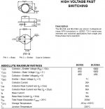
noyan emailed me and asked me about wether it is alright to use a BUX98A in this PS. He sent me the data sheet which i did a screen shot of, and cropped down to attach here.
i told him to come here and see what other people have to say, but for now i am saying (guessing) that based on the ratings of this device, he should be fine to use it with a voltage doubler as oposed to a straight bridge safely because it looks like it is used as a sort of floating regulator, where it's referenced off higher voltage than ground, so pot. diff on all conections should be within ratings right???
cheers
Attachments
866 tube power supply
Hi,
I also want to make the 813SE UL amp.
For the 900V B+, i will use 866 tube.
I want to use the CLC filter after the 866.
As I know, the first capacitor after 866 cannot use too large.
So what is the bigger value for the first capacitor?
If I use LC filter, what is the VAC is I want 900V B+?
Thanks.
benny said:
just remember when refering to power, we are refering to P = VI in this case (it's a slightly different equation for AC, but this is DC here)... this amp is only 900V and 100mA, so P = 900 x 0.1 = 90W... not a lot of power... just thought i'd point that out... probably just a mistake you made, but if it was what you thought, then hope i helped you out.
cheers
Thanks Benny. I assumed he meant 100mA per channel. If you add 200mA plus whatever the driver stages utilize it does start to add up a little. It's definately more power than I have ever designed for.
Cree Schottkys
Spec sheets look interesting, Eli. Do you know where these diodes can be purchased?
Eli Duttman said:The "recent" introduction of high PIV Silicon Carbide (SiC) Schottky diodes by Cree is a milestone in SS rectified B+ supplies. Unlike PN devices, Schottky diodes do not exhibit a reverse recovery spike; therfore, they are dead quiet. Until the SiC parts were introduced, Schottkys were strictly a low voltage proposition suited to heater supplies only.
Spec sheets look interesting, Eli. Do you know where these diodes can be purchased?
- Status
- This old topic is closed. If you want to reopen this topic, contact a moderator using the "Report Post" button.
- Home
- Amplifiers
- Tubes / Valves
- 900v. 100ma. Power supply for 813 tube amplifier