Few weeks ago I had a friend over at my place and I showed him a PP amp, with ECC82 as voltage and phase splitter and two 12BH7A as output tubes, driven through Frank's WCF pre-amp. He felt in love with the sound (used to hear a SS HK 655Vxi) and asked me to build something similar for him. I already have an OTL in construction, but put it aside to build a pre + 2 power monoblocks for him.
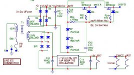
To make a long story short. Electricity companies in Brazil are allowed to float their voltage supply within a +/- 10%, but it's not unusual that it will float even more. For this reason I decided to go to regulated PS for B+ (and for heaters). For the preamp I'm using a ECL82 + zener (sorry Frank) regulator. For the power I wanted to use the schematic below, disponible at the site http://members.tripod.com/richard984/6as7_pp.htm. 255V is what I need for my amp and a "a long time constant on the B+ regulation fets" comes in handy. The designed PS delivers something between 250mA and 300mA (for both channels), while mine will have to deliver around 100mA (each monoblock).
The questions: is it possible to change the IRFBG30 (1000V / 3.1A 5R 125W) for a IRFBE30 ( 800V / 4.1A / 125W)? I’m no expert at mosfet’s, but it seems that the IRFBE30 would be sufficient (voltage and current wise).
Richard says that the cap (C11 in the schematic) in front of the regulators must be a non inductive one so the output resistance of the PS keeps low. I was thinking about using 60muF of motor start caps...are those non inductive?
Attachments
Safety issue...
Yes ..it is perfectely safe to use the IRFBE30 in your circuit!
Regards
The questions: is it possible to change the IRFBG30 (1000V / 3.1A 5R 125W) for a IRFBE30 ( 800V / 4.1A / 125W)?
Yes ..it is perfectely safe to use the IRFBE30 in your circuit!
Regards
Re: fast reply
De nada!")
The regulator with the mosfet is the same style ,that Tehcnics call virtual batery operation.
As the gate of the Mosfet draws no current it is possible to use a very high value of resistor for polarisation...4,7 M .... and because of that ,to have a very good rejection of supply noise.
Um abraço.
ErikdeBest said:Olá Jorge
Obrigado pela resposta.
Erik
De nada!
The regulator with the mosfet is the same style ,that Tehcnics call virtual batery operation.
As the gate of the Mosfet draws no current it is possible to use a very high value of resistor for polarisation...4,7 M .... and because of that ,to have a very good rejection of supply noise.
Um abraço.
Yesterday I concluded the regulated PS using the IRFBE30. Richard Sears, who designed it, says it has a "long time constant on the B+ regulation fets". Well, it really have. After 30 minutes drawing about 50mA of the B+ it had arrived at 130VDC of the 255VDC.
How could I decrease this time? Or shall there be something else going wrong?
Erik
How could I decrease this time? Or shall there be something else going wrong?
Erik
What COULD happen is that the cap has a slight leakage current. Also, the zeners normally take more than a mA before coming to their advertised voltage. it may well be that at the very small current available from the 4.7 meg they take all that current before coming up to voltage. Any of those two tings (and probably a few others) could explain the long charging time. Try with 470k instaed of 4.7meg. If that works, you know the causes. And with 470k you still have massive noise and ripple attenuation.
Jan Didden
Jan Didden
Me "being smart"
Thanks for the reply Janneman. (My father use to call me this way sometimes.)
I solved the problem...measured voltage after the 4M7 resistor and that was raising to low due to... 44muF of capacitance. Changed this for 3 muF film capacitors and now the circuit is working fine.
Erik
Thanks for the reply Janneman. (My father use to call me this way sometimes.)
I solved the problem...measured voltage after the 4M7 resistor and that was raising to low due to... 44muF of capacitance. Changed this for 3 muF film capacitors and now the circuit is working fine.
Erik
Hi Janneman
You're right, my father is Dutch and my mother half Dutch, half brazilian. They live in Brazil for more than 25 years now.
In a few weeks I will change the Brazilian flag for the Dutch one, as I'm going back to the Netherlands to conclude my ME graduation.
Good weekend.
Erik
You're right, my father is Dutch and my mother half Dutch, half brazilian. They live in Brazil for more than 25 years now.
In a few weeks I will change the Brazilian flag for the Dutch one, as I'm going back to the Netherlands to conclude my ME graduation.
Good weekend.
Erik
- Status
- This old topic is closed. If you want to reopen this topic, contact a moderator using the "Report Post" button.
- Home
- Amplifiers
- Tubes / Valves
- mosfet in regulated PS.