Hi all,
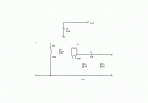
I've decided that I need to build a Buffer linestage instead of a plate follower linestage since I need no gain. Merely impedance matching. While I have designed plate followers and understand how tp bias them this will be the first cathode follower circuit I have tried. I would like to bias the 5687 at 20mA (a cathode follower sounds better at high current from what I understand) but I'm not sure about how to calculate the cathode resistor in order to achieve this. Would anyone care to give me a lesson in cathode followers? Pretty please.


Gavin
I've decided that I need to build a Buffer linestage instead of a plate follower linestage since I need no gain. Merely impedance matching. While I have designed plate followers and understand how tp bias them this will be the first cathode follower circuit I have tried. I would like to bias the 5687 at 20mA (a cathode follower sounds better at high current from what I understand) but I'm not sure about how to calculate the cathode resistor in order to achieve this. Would anyone care to give me a lesson in cathode followers? Pretty please.
Gavin
Attachments
This is a type of cathode follower that naive builders have done many times and has given CFs an undeserved bad reputation. You need to be dropping some serious voltage across the cathode resistor, and that means either returning it to a negative rail or biasing up the grid with a voltage divider and capacitively coupling the input.
Let's say you want to go the negative rail route. And you've got -200V available. If the grid is roughly at ground, the cathode will be roughly at ground (within a few volts). So for a desired current, you size the cathode resistor according to Ohm's Law. Want 20 ma? Then for a 200V drop across the resistor, R = 200V/20ma = 10kohm.
Let's say you want to go the negative rail route. And you've got -200V available. If the grid is roughly at ground, the cathode will be roughly at ground (within a few volts). So for a desired current, you size the cathode resistor according to Ohm's Law. Want 20 ma? Then for a 200V drop across the resistor, R = 200V/20ma = 10kohm.
Sch3mat1c said:Yeah, the way I do something floating like that is instead of a grid leak to ground, I use two leaks, one to +V and the other to ground.
Tim
That works fine, but you do have to capacitively couple the input. Depending on the application and one's religion, that may or may not be a disadvantage.
Sch3mat1c said:Yeah, the way I do something floating like that is instead of a grid leak to ground, I use two leaks, one to +V and the other to ground.
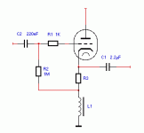
Yes, sometimes, you're forced to do it that way, but it does inject HT noise directly into the grid. A quieter approach is to add a small cathode bias resistor in series with the main cathode load, then take a 1M grid-leak from there up to the grid. Not only does this give better rejection of HT noise, but the 1M resistor is bootstrapped, making it appear much larger, giving a higher input impedance, which can sometimes be useful.
Bootstrapping is positive feedback, so if you use it, a grid-stopper resistor is a good idea. A grid-stopper is a resistor soldered between the grid and all other grid connections. It should be soldered so that its body is only 2mm away from the grid pin (the inductance of even a short bit of wire is significant at VHF). 1k is usually sufficient, but if you don't have an oscilloscope (to check that it worked), 4k7 might be a good idea. Use a carbon film resistor (lowest inductance at RF).
Hi,
The best way to hook up a CF for a buffer in a pre amp is the old fashioned way of using a good quality choke IMHO. You don’t need 20 mA, 5 mA to 10 mA will suffice. The idling current depends largely on the load resistor which is usually high ( >100K ).
Cheers
The best way to hook up a CF for a buffer in a pre amp is the old fashioned way of using a good quality choke IMHO. You don’t need 20 mA, 5 mA to 10 mA will suffice. The idling current depends largely on the load resistor which is usually high ( >100K ).
Cheers
Attachments
The circuit that Pjotr provided is an EXCELLENT starting point for a buffered volume control.
Replace the I/P coupling cap. and grid leak resistor with a 100 K Ohm pot. Obviously, the wiper of the pot. gets connected to the grid stopper resistor. You can replace R3 (the cathode bias resistor) with a stack of 3X red LEDs. Such a stack places the cathode at a "perfect" 6 V. above the grid. The full 2 V. RMS O/P of a CDP is 5.66 V. peak to peak. With 6 V. of grid bias, a CDP will not clip the grid circuit.
The inductive reactance of the loading choke at 20 Hz. should be at least 3X Rp. A good alternative to a loading choke is a constant current sink (CCS). You can construct a CCS from either a MOSFET or a pentode. In pentodes, the 6AU6 is fine for modest current, while the 7054 is good for currents too large for the 6AU6 to handle. A single "bottle" solution to a CCS loaded CF is the 6BM8. The triode in the 6BM8 is 1/2 a 12AT7. The power pentode in the 6BM8 will LOAF at 12AT7 currents.
Increase the O/P coupling cap. to 4.7 muF., as that value accomodates low (10 K) I/P impedance loads.
I guess I should have been more specific about my needs. I am using a Parasound preamp with my SE EL84 amp at the moment. I drive the amp and a M&K subwoofer amp with the preamp. I wanted to go all tube but I was concerned that a anode follower circuit would not drive the two parallel loads (plus I don't need all of the gain). THat is why I wanted to use a buffered volume control. With the low output impedance of a buffer I wouldn't be concerned about the lower than optimal load that it would be operating into. I may have this all wrong and my original preamp circuit would work fine. Opinions?
Gavin
Gavin
Not that difficult.
No, you don't. How about opening it up and having a look? A typical transistor amplifier has an input electrolytic capacitor of about 10uF connected to the input connector, followed by a resistor connected to 0V. The typical value of that resistor is between 5k and 47k. All you need to do is to find that resistor, and read its colour code. Its value is the input impedance.
G said:The amp is integrated into the subwoofer cabinet and I lack the equipment to test for input impedance.
No, you don't. How about opening it up and having a look? A typical transistor amplifier has an input electrolytic capacitor of about 10uF connected to the input connector, followed by a resistor connected to 0V. The typical value of that resistor is between 5k and 47k. All you need to do is to find that resistor, and read its colour code. Its value is the input impedance.
EC8010 said:Yes, sometimes, you're forced to do it that way, but it does inject HT noise directly into the grid.
Iff your signal source is on par with the impedance of the grid circuit. A 100k pot (at middle setting) or 12AX7 plate might be iffy, anything lower impedance will be more than sufficient. And besides, you're supposed to be designing PSU's far better than that, mmm??
Tim
Pjotr said:Hi,
The best way to hook up a CF for a buffer in a pre amp is the old fashioned way of using a good quality choke IMHO. You don’t need 20 mA, 5 mA to 10 mA will suffice. The idling current depends largely on the load resistor which is usually high ( >100K ).
Cheers
This circuit will work great but given you are driving maybe 5V max. and have 250VDC to spare, a resistor instead of the inductor will save time.
Tim
Gavin,
Stop giving yourself a headache. The O/P impedance of a 5687 CF is < 150 Ohms. The rule of thumb is that the device(s) being driven should have a net I/P impedance at least 10X of the O/P impedance. I seriously doubt that the M&K SW's I/P impedance is as low as 5 KOhms. The IHF "standard" is 10 KOhms. I would expect a reputable company, like M&K, to meet or better the IHF "standard".
BTW, TDSL shows the 5687 with Ua = 180 V. and Ug = -7 V. to have an Ia of 23 mA. A 150 V. Ua and a -6 V. Ug from 3X red LEDs will be awfully close to the 20 mA. you want. If you use a 20 mA. CCS, 3X red LED bias, and a 225 V. B+ rail, things will fall into place "automatically".
G.,
The CCS doesn't have to be as sophisticated as the 1 in your headphone circuit. A high working voltage N channel enhancement MOSFET will do the job. Put a 100 Ohm resistor (as a test point) between the source and ground. A 1 MOhm pot. between B+ and ground with the wiper connected to the gate forms the adjustment. Start with the gate at ground and raise the forward bias until the drop across the 100 Ohm resistor is 2.0 V.
BTW, a well regulated power supply is in order. A "simple" choke I/P filter will get the job done.
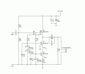
Hi Gavin,
Think the headphone amp will suit your needs perfectly. But I would make some modifications. I would set the current trough the given fet at 10-20 mA max and lower R2 too 200K so the gate of the fet sits at 10V. Also R3 an R4 can be much higher, 5 mA is more than sufficient through the leds. For driving long cables I would put a resistor of 220 ohms in series with the output caps. This eliminates any possible oscillations due to capacitive loading (this also holds for a CF).
That’s true, but then I would choose a resistor large enough to have 50 – 100V DC at the cathode. Then the resistor acts more or less as a constant current source. Disadvantage is that the DC voltage at the cathode drifts when Gm drifts due to ageing but that is not a big disadvantage. The advantage of a choke is that the cathode can swing large amounts below ground without a negative supply and still the bias current can be high.
Cheers
Think the headphone amp will suit your needs perfectly. But I would make some modifications. I would set the current trough the given fet at 10-20 mA max and lower R2 too 200K so the gate of the fet sits at 10V. Also R3 an R4 can be much higher, 5 mA is more than sufficient through the leds. For driving long cables I would put a resistor of 220 ohms in series with the output caps. This eliminates any possible oscillations due to capacitive loading (this also holds for a CF).
This circuit will work great but given you are driving maybe 5V max. and have 250VDC to spare, a resistor instead of the inductor will save time.
Tim
That’s true, but then I would choose a resistor large enough to have 50 – 100V DC at the cathode. Then the resistor acts more or less as a constant current source. Disadvantage is that the DC voltage at the cathode drifts when Gm drifts due to ageing but that is not a big disadvantage. The advantage of a choke is that the cathode can swing large amounts below ground without a negative supply and still the bias current can be high.
Cheers
Eli Duttman said:G.,
The CCS doesn't have to be as sophisticated as the 1 in your headphone circuit. A high working voltage N channel enhancement MOSFET will do the job. Put a 100 Ohm resistor (as a test point) between the source and ground. A 1 MOhm pot. between B+ and ground with the wiper connected to the gate forms the adjustment. Start with the gate at ground and raise the forward bias until the drop across the 100 Ohm resistor is 2.0 V.
BTW, a well regulated power supply is in order. A "simple" choke I/P filter will get the job done.
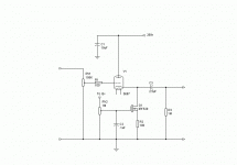
I believe you are talking about something like this. I suppose I would use LEDs to bias the FET once I figure out the voltage needed at the gate though.
Attachments
G.,
The most recent schematic is very close. Assuming a well regulated B+ rail, C1 is unnecessary. R1, the grid stopper, should be 1 KOhm Carbon comp. You need to provide -6 V. of grid bias; either a stack of 3X red LEDs or a 300 Ohm resistor in the line between the 5687's cathode and the FET's drain will do the job. The "bottom" of the 100 KOhm volume control gets connected to the FET's drain, not ground.
The most recent schematic is very close. Assuming a well regulated B+ rail, C1 is unnecessary. R1, the grid stopper, should be 1 KOhm Carbon comp. You need to provide -6 V. of grid bias; either a stack of 3X red LEDs or a 300 Ohm resistor in the line between the 5687's cathode and the FET's drain will do the job. The "bottom" of the 100 KOhm volume control gets connected to the FET's drain, not ground.
- Status
- This old topic is closed. If you want to reopen this topic, contact a moderator using the "Report Post" button.
- Home
- Amplifiers
- Tubes / Valves
- Biasing a cathode follower?


