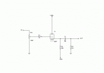
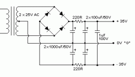
Gavin, why don't you try this?
I thought I already described that, post 27.
I dont really understand why you post all these fancy CCS based and choke base designs for something as basic as a follower, in reality it is not possible to distinguish measurements vise between a CF using 100V over a resistor and a Cf using a CCS, in addition to that no CCS is transparent and will have some influence on the sound, why use SS when it is not needed?
Hans
Right Federico (and Hans  ),
),
But is R4 not a bit low? You will exceed the max. cathode heater voltage of 100V then if the heater is at gnd potential. 470 ohms is more appropriate IMO with a B+ of 200V and for a B+ of 250V I'll come to 680 ohms. Also I would make the grid stopper R3 1K and R5 1M.
Indeed SY, a diode will take care of that and I have seen that applied in some circuits but then connected between grid and cathode.
Anyway Gavin must have now enough inspiration for experimenting
Indeed SY, a diode will take care of that and I have seen that applied in some circuits but then connected between grid and cathode.
I just breadboarded the circuit without a diode and switched the positive supply on and off. No problem with the tube (a 6SN7)- the grid leak resistor does a fine job on its own to limit the current in the event of failure.
But is R4 not a bit low? You will exceed the max. cathode heater voltage of 100V then if the heater is at gnd potential.
Who says it must be at ground potential? or you can use negative voltage as SY indicated before, this is what I use in my preamp, (I use DC coupled stages so the output and input is at ground potential).
The security concersn you raise PJOTR I think is very exagurated , in reality if the B+ goes down the B- goes down also as they are likely to come from the same power supply, in any case the risk is extremely small that something like that should happen.
Hans
Duh Hans?
I just questioned the dimensioning of Federico’s circuit. And no there are no rules that commands the heater at gnd potential but it usually is. And is just app. 80V across the tube not a bit low?
I did not questioned SY’s circuit itself, just made a side note. We are experimenting you know and a small mistake should not fry the tube.
Cheers
Why CCS loading of a cathode follower? CCS loaded cathode followers sound GOOD; that's why. Choke loaded CFs sound good too. A good number of people dislike the sound of resistively loaded cathode followers.
For those individuals who simply can't abide "sand", either a 6AU6 or a 7054, depending on the current being handled, will get the job done.
As for measurements, Recklinghausen's remarks bear repeating. "If it measures good and sounds bad, it is bad." "If it measures bad and sounds good, you are measuring the wrong things."
A good number of people dislike the sound of resistively loaded cathode followers.
Yes, so many are designed so badly. And so many people are willing to jump to conclusions based on a limited data set. A properly designed resistor-loaded CF operated within its limits is pretty darn transparent to the ear.
Sorry, not directed at you, Eli, just my particular pet peeve.
Federico's circuit is very, very good.
One further suggestion; reduce the grid leak to 150K. This resistor is bootstrapped anyway, so input impedance remains in the megohm range, permitting a small coupling cap, preferably of foil polystyrene.
The most significant issues for this circuit are operating points; Vak and Ip. Getting it right is most imporant, and for even line level, the points chosen are far less tolerant than a plate loaded triode. This is, in my view, the reason the CF gets such a bad rap; operating point is more critical. And once you talk of chokes, while B+ can be much lower, cost is far higher. Give me a slightly higher B+ and a resistor any day......
Cheers,
Hugh
Hi All,
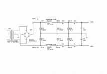
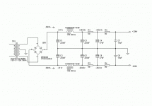
I would like to pursue Sy's idea. It seems simple and elegant to me. Here is what I have supply wise and circuit wise. I've never tried to build a bipolar supply so if I made any glaring mistakes please let me know. As far as the circuit goes I would like to have a good sounding buffer with the least amount of parts necessary. Being as I don't understand the basic principals involved in biasing a CF I'm incorporating your educated opinions and ideas into this design. I'm going to read up on CF as soon as I have enough peace and quiet long enough to do so. Thanks for all of your input.
I would like to pursue Sy's idea. It seems simple and elegant to me. Here is what I have supply wise and circuit wise. I've never tried to build a bipolar supply so if I made any glaring mistakes please let me know. As far as the circuit goes I would like to have a good sounding buffer with the least amount of parts necessary. Being as I don't understand the basic principals involved in biasing a CF I'm incorporating your educated opinions and ideas into this design. I'm going to read up on CF as soon as I have enough peace and quiet long enough to do so. Thanks for all of your input.
Attachments
Hi Frank. I'm not following. The polarity of the caps on the negative side are the reverse of those on the positive side. I would want to connect the positive side of the electrolytic caps on the negative half of the supply torwards the ............... never mind. I see what you are talking about. Thank you.


For me it's not really a matter of complexity. I'm not very familiar with SS electronics practically speaking. I'm also a perfectionist when it comes to building something. I would want to have professionally made CCS boards. I would then have to worry about heatsinks and mounting kits ...................etc. This is the simplest solution for me personally. I'm sure that using a CCS has a lot of advantages. When I get my little workshop put together and I get a proper breadboard apparatus built I will certainly be trying out some CCS loaded circuits. Please don't take my decision as a slight to you or your opinions.
Einstein, as usual, was right. Simplicity is good, but some complexity is needed for proper performance.
Both the CCS and bipolar supply circuits will PERFORM. There IS more than 1 way to skin a cat.
A suggestion for that bipolar supply, make the 1st filter caps. after the bridge 22 muF. and make the capacitance in the 2nd position 440 muF. While large value caps. in the 1st position are not a problem for SS diodes, they are a potential problem for the power trafo. I^2R loss heating in the trafo goes up when large caps. are used in the 1st position. 22 muF. is PLENTY for keeping the rail voltage up, while allowing the trafo to run cool.
Eli Duttman said:Einstein, as usual, was right. Simplicity is good, but some complexity is needed for proper performance.
Both the CCS and bipolar supply circuits will PERFORM. There IS more than 1 way to skin a cat.
A suggestion for that bipolar supply, make the 1st filter caps. after the bridge 22 muF. and make the capacitance in the 2nd position 440 muF. While large value caps. in the 1st position are not a problem for SS diodes, they are a potential problem for the power trafo. I^2R loss heating in the trafo goes up when large caps. are used in the 1st position. 22 muF. is PLENTY for keeping the rail voltage up, while allowing the trafo to run cool.
I will do exactly that. Thanks Eli. I have a question about the CF biasing. If I want 20mA of current and I want to drop half of the available voltage across the cathode resistor then I would need a 200/.02 = 10K resistor. Since I'm dropping half the voltage across the cathode resistor then according to our old friend Kirchoff I must be dropping the remaining half of the available voltage across the tube at 20 mA. That would mean the Grid is sitting at -100v when compared to the cathode correct?
No, the grid will sit at ground, the cathode will be at roughly 5-10 volts, the plate will be at 200 volts, and the tube will be operating in a happy place.
I think you're a little overboard on the supply, but that's relatively harmless. Once you have the basic circuit up and running, you can start playing around with current sources, servoes, and all kinds of wonderful creatures.
I think you're a little overboard on the supply, but that's relatively harmless. Once you have the basic circuit up and running, you can start playing around with current sources, servoes, and all kinds of wonderful creatures.
- Status
- This old topic is closed. If you want to reopen this topic, contact a moderator using the "Report Post" button.
- Home
- Amplifiers
- Tubes / Valves
- Biasing a cathode follower?


