Don't Try This At Home ! ")
Ok here's what I came out with just to make sure that understand a little what going on
I didn't put any regulator because I'm a bit mixed up about it. I mean, where can you find regulator that accepts 250VDC ? Is there something to do with floating ground stuff ?
Well, here's my progress. I tried to do my best to achieve 250VDC but I have serious problems with current capacity of the rectifier. My load resistance is too low ?
Well, gotta go to bed !
I hope to have news from you soon !
Ok here's what I came out with just to make sure that understand a little what going on
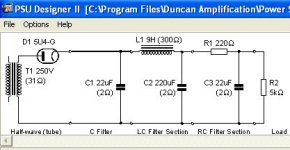
So, if we have the 5U4 with a 250V CT xformer and a cap input filter (AKA CLC) we can have about 330VDC after the cap, add a choke with a DCR of about 300R followed by another filter cap and perhaps a pi filter (AKA CRC) to lower the B+ and ripple to desired levels and we can feed the regulator and come out with a superdeluxe 250VDC with some voltage margin in case you want to recycle it for another project.
I didn't put any regulator because I'm a bit mixed up about it. I mean, where can you find regulator that accepts 250VDC ? Is there something to do with floating ground stuff ?
Well, here's my progress. I tried to do my best to achieve 250VDC but I have serious problems with current capacity of the rectifier. My load resistance is too low ?
Well, gotta go to bed !
I hope to have news from you soon !
Attachments
Hi,
Well if you look at the tube regulator as posted here:
250VDC REG.
You'll see that there's no need to float a semi-conductor in the HT line.
The sim shows a half-wave rectifier.
What you need to simulate with the program is a full-wave rectifier.
You need a 250-CT-250 VAC powerxformer with the CT grounded feeding a capacitor input filter followed by a choke and cap (CLC).
Here's an example of an amplifier using such a supply:
VT 52 SRPP
On the same site there are a few other examples of this.
Cheers,
I didn't put any regulator because I'm a bit mixed up about it. I mean, where can you find regulator that accepts 250VDC ? Is there something to do with floating ground stuff ?
Well if you look at the tube regulator as posted here:
250VDC REG.
You'll see that there's no need to float a semi-conductor in the HT line.
I tried to do my best to achieve 250VDC but I have serious problems with current capacity of the rectifier. My load resistance is too low ?
The sim shows a half-wave rectifier.
What you need to simulate with the program is a full-wave rectifier.
You need a 250-CT-250 VAC powerxformer with the CT grounded feeding a capacitor input filter followed by a choke and cap (CLC).
Here's an example of an amplifier using such a supply:
VT 52 SRPP
On the same site there are a few other examples of this.
Cheers,
Tweaked 6SN7 VTV
Hi Folks,
For ideas you might check out AlbuquerqueAudio's
tweaked 6SN7 VTV:
http://mywebpages.comcast.net/gillespie147/6SN7-Preamp.html
I have no experience with or endorsement of
this design--it just looks interesting.
Best,
George Ferguson
Hi Folks,
For ideas you might check out AlbuquerqueAudio's
tweaked 6SN7 VTV:
http://mywebpages.comcast.net/gillespie147/6SN7-Preamp.html
I have no experience with or endorsement of
this design--it just looks interesting.
Best,
George Ferguson
Frank;
At the risk of thread-jacking, would you please elaborate on your comments on the Blue Velvet Preamp? It looked fairly normal to me and I woundered what I missed.
Thanks.
Doug
At the risk of thread-jacking, would you please elaborate on your comments on the Blue Velvet Preamp? It looked fairly normal to me and I woundered what I missed.
It looks like a bit of an oddball, both the PS and the circuit itself.
Thanks.
Doug
Power Supply
Frank & Elkaid,
If we have people talking about building a 6SN7 or 12SN7 based linestage with ~250V B+ and capable of 6/12 filaments, why not just start with the original VTV design and adjust the power supply resistors to 250V? The original design delivers ~330V B+ (note typo in article - says 370V) and is setup, depending on whether you wire the filaments in parallel or series to use either 12SN7 or 6SN7 tubes. It also has the advantage that the PS is dead quiet and is simple enough that just about anybody can get it to work.
Just a thought -ALBQ
Hi,
Nothing major, really.
Just some stuff that struck me as not very accurate:
From:
BLUE VELVET
Filaments aren't supposed to emit, the cathodes they're heating are...
Not so on the 6SN7s I've seen so far and either way it's just a cosmetic issue...
The heater surface is coated for softstart and put deeper into the cathode sleeve to prevent this from being seen by the user, it is otherwise purely aesthetic.
Certainly, lightbulbs can last longer when softstarted but they can and do fail just the same and they're lightbulbs, not filaments.
With tubes, it's the getter that gets exhausted first.
Hmmm...I seriously doubt that.
Fine, but what about R3?
Sorry, that just ain't true unless you want to cal 1mV of wideband noise noisy.
Ah, yes...bye,bye shunt reg.
As said, nothing major...just me frowning a bit on their reasoning and design decisions.
Read it again if you like, it reads almost like a TAS review...nice but not a very accurate description of what does what...
No doubt it sounds a lot better than I make it sound...
Ciao,
It looked fairly normal to me and I woundered what I missed.
Nothing major, really.
Just some stuff that struck me as not very accurate:
From:
BLUE VELVET
Criterion #5 follows logically on the heels of #4, as it is important to stabilize filament emission.
Filaments aren't supposed to emit, the cathodes they're heating are...
You've no doubt seen pre-amplifier tubes light up like light bulbs after power is turned on.
Not so on the 6SN7s I've seen so far and either way it's just a cosmetic issue...
The heater surface is coated for softstart and put deeper into the cathode sleeve to prevent this from being seen by the user, it is otherwise purely aesthetic.
Certainly, lightbulbs can last longer when softstarted but they can and do fail just the same and they're lightbulbs, not filaments.
With tubes, it's the getter that gets exhausted first.
A happy middle ground was sought at 50% of the thermal rating to balance sonics against life time.
Hmmm...I seriously doubt that.
Much of the anode follower's output is returned to the grid via resistor R4. That's local feedback to the tune of about 15 dB which linearizes the compound amplifier and reduces output impedance to around 400 ohms.
Fine, but what about R3?
Gas regulator tubes are notoriously noisy creatures
Sorry, that just ain't true unless you want to cal 1mV of wideband noise noisy.
Kara's preferred solution was the addition of a plate decoupling circuit (R5/C4 in the power supply schematic) to better isolate the power supply from the BV outputs.
Ah, yes...bye,bye shunt reg.
As said, nothing major...just me frowning a bit on their reasoning and design decisions.
Read it again if you like, it reads almost like a TAS review...nice but not a very accurate description of what does what...
No doubt it sounds a lot better than I make it sound...
Ciao,
Hi,
How? By shorting out R1, R2?
Fine by me, I intended to have Elkaid do something like that or use a 7812 + 7806 in series and make the output switchable.
The 78xx should also have a protective diode across them, just in case.
Admittedly, I often forget to use those myself...
As for the PS, why not use a series regulator instead?
The shunt they use now is only clamping the rail locally as it is set up now.
Better than nothing at all, certainly.
Cheers,
and is setup, depending on whether you wire the filaments in parallel or series to use either 12SN7 or 6SN7 tubes.
How? By shorting out R1, R2?
Fine by me, I intended to have Elkaid do something like that or use a 7812 + 7806 in series and make the output switchable.
The 78xx should also have a protective diode across them, just in case.
Admittedly, I often forget to use those myself...
As for the PS, why not use a series regulator instead?
The shunt they use now is only clamping the rail locally as it is set up now.
Better than nothing at all, certainly.
Cheers,
Please don't laugh...
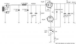
Here's what I came up with...
I don't know if it would work... The values are probably totally incorrect but it would be nice if someone could validate and/or touch-up the schematic a bit...
Are all those resistors/capacitors necessary ? I hope not
Here's what I came up with...
I don't know if it would work... The values are probably totally incorrect but it would be nice if someone could validate and/or touch-up the schematic a bit...
Are all those resistors/capacitors necessary ? I hope not
Attachments
Hi,
Should be fine...
You can drop the 470R resistor and the two 330µF caps.
Depending on the powerxformer you use you may end up with too much voltage prior to the regulator but nothing that can't be fixed in a simple manner.
Cheers,
EDIT: You won't forget the heater for the 5U4G and the regulator?
Should be fine...
You can drop the 470R resistor and the two 330µF caps.
Depending on the powerxformer you use you may end up with too much voltage prior to the regulator but nothing that can't be fixed in a simple manner.
Cheers,
EDIT: You won't forget the heater for the 5U4G and the regulator?
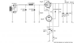
Another try...
Here we go...
Here's the potential candidates for the Transformer position:
from Hammond
269EX 190-0-190 65mA 6.3 V@2.5 A
269GX 225-0-225 65mA 6.3 V@2.5 A
270AX 240-0-240 50mA 6.3 V@2.5 A
269JX 250-0-250 60mA 6.3 V@2.5 A
Which model should I go for ? You seemed to mention that 250-0-250V would be a bit too high for the regulator ? Would 50-60mA be enough ?
6SN7 tubes draw around 0.6A each so I'll need around 1.2A right ? Existing 6.3V winding should be enough. Enough headroom for an additional heaphone stage tube I hope.
Also, I'll need a separate 5V supply for the two 5U4G tube
(3A filament X 2 = 6A...ouch)
Finally, which voltage C1 & C2 should be rated ?
Did I make any mistake ? I'll probably order parts as soon as I get a "OK" confirmation from qualified people (hmmm well, you guys)
Thank you alot !
Here we go...
Here's the potential candidates for the Transformer position:
from Hammond
269EX 190-0-190 65mA 6.3 V@2.5 A
269GX 225-0-225 65mA 6.3 V@2.5 A
270AX 240-0-240 50mA 6.3 V@2.5 A
269JX 250-0-250 60mA 6.3 V@2.5 A
Which model should I go for ? You seemed to mention that 250-0-250V would be a bit too high for the regulator ? Would 50-60mA be enough ?
6SN7 tubes draw around 0.6A each so I'll need around 1.2A right ? Existing 6.3V winding should be enough. Enough headroom for an additional heaphone stage tube I hope.
Also, I'll need a separate 5V supply for the two 5U4G tube
(3A filament X 2 = 6A...ouch)
Finally, which voltage C1 & C2 should be rated ?
Did I make any mistake ? I'll probably order parts as soon as I get a "OK" confirmation from qualified people (hmmm well, you guys
)Thank you alot !
Attachments
Hi,
Are you planning on using two 5U4Gs in a single power supply or just one?
The 5U4G being a full-wave rectifier you normally only need one .
Unless you want to go the full hog and build a dual mono preamp from the PS upwards?
In the latter case you just make everything twice.
As for the powerxfromer, you're better of starting with too much voltage than too little.
Depending on the current rating of the xformer and the current drawn by the circuit the voltage will go either up or down: undercurrent spec voltage will sag and powerxformer will get hot.
Overcurrentspec, the voltage will rise. No big deal here as the choke and regulator will burn it off.
For the regulator to work properly you need to have at least a 50V drop across it, more won't hurt within reason. (heater to cathode insulation can become a concern)
If it were me, I'd rate the filtercaps at 400VDC to be safe.
As SY points out the rectified voltage will be around 310-320VDC, add the drop of the choke and it'll be just about O.K.
Again, IMO you may be better of starting a little on the high side.
So, if hammond or whatever the supplier has a suitable 260-CT-260V xformer I'd go for that one.
As for the heater consumption: the regulator is best supplied from a dedicated winding so you'll need a 6.3V .875mA (1A is O.K.) per regulator.
A 5U4G needs 5V 3A, a bit more won't hurt.
A 6SN7 requires 6.3V @ 600mA but we'll like to be able to use a 12SN7 as well and use DC, so a 15V secondary @ 1A being common as mud I'd spec one xformer with two such windings, one per channel.
FW bridge rectified and filtered we can than use a 7812 2A reg and a power resistor to set the voltage at 6.3V as per the Blue Velvet preamp but there are many alternate ways.
Cheers,
Also, I'll need a separate 5V supply for the two 5U4G tube
Are you planning on using two 5U4Gs in a single power supply or just one?
The 5U4G being a full-wave rectifier you normally only need one .
Unless you want to go the full hog and build a dual mono preamp from the PS upwards?
In the latter case you just make everything twice.
As for the powerxfromer, you're better of starting with too much voltage than too little.
Depending on the current rating of the xformer and the current drawn by the circuit the voltage will go either up or down: undercurrent spec voltage will sag and powerxformer will get hot.
Overcurrentspec, the voltage will rise. No big deal here as the choke and regulator will burn it off.
For the regulator to work properly you need to have at least a 50V drop across it, more won't hurt within reason. (heater to cathode insulation can become a concern)
If it were me, I'd rate the filtercaps at 400VDC to be safe.
As SY points out the rectified voltage will be around 310-320VDC, add the drop of the choke and it'll be just about O.K.
Again, IMO you may be better of starting a little on the high side.
So, if hammond or whatever the supplier has a suitable 260-CT-260V xformer I'd go for that one.
As for the heater consumption: the regulator is best supplied from a dedicated winding so you'll need a 6.3V .875mA (1A is O.K.) per regulator.
A 5U4G needs 5V 3A, a bit more won't hurt.
A 6SN7 requires 6.3V @ 600mA but we'll like to be able to use a 12SN7 as well and use DC, so a 15V secondary @ 1A being common as mud I'd spec one xformer with two such windings, one per channel.
FW bridge rectified and filtered we can than use a 7812 2A reg and a power resistor to set the voltage at 6.3V as per the Blue Velvet preamp but there are many alternate ways.
Cheers,
Are you planning on using two 5U4Gs in a single power supply or just one?
My mistake
Only one.So, if hammond or whatever the supplier has a suitable 260-CT-260V xformer I'd go for that one.
Nice, They got one :
270DAZ 76VA 260-0-260 90mA 6.3 V@3.5 A
90mA should be enough current for your 6SN7 preamp right ?
In a first attempt, I'll go the single supply route... I'll leave the option opened for a dual supply.
As for the choke, 40mA will probably be not enough isn't it ?
(I'm refering to the following : Hammond 156G 9H 40mA 300ohms)
Otherwise, there's Hammond 157M 8H 100mA 259ohms Would it be more appropriate ?
Thanks guys
Hi,
Should be.
I'd go for that one.
Here's the deal: use one rectifier, choke and caps, split to two regulators, one per channel and you'll never have this nagging "what if" feeling and no worries about crosstalk between channels.
Cheers,
90mA should be enough current for your 6SN7 preamp right ?
Should be.
Otherwise, there's Hammond 157M 8H 100mA 259ohms Would it be more appropriate ?
I'd go for that one.
I'll leave the option opened for a dual supply.
Here's the deal: use one rectifier, choke and caps, split to two regulators, one per channel and you'll never have this nagging "what if" feeling and no worries about crosstalk between channels.
Cheers,
If it is within your budget try to shoot for a 3xx series Hammond...
They have electrostatic shields...40dB of armour against nasty hf rubbish that is capacitively coupled to the secondary windings.
Don't know what the other "extra's" are between 2xx and 3xx series..
Cheers,
Bas
They have electrostatic shields...40dB of armour against nasty hf rubbish that is capacitively coupled to the secondary windings.
Don't know what the other "extra's" are between 2xx and 3xx series..
Cheers,
Bas
Here's the deal: use one rectifier, choke and caps, split to two regulators, one per channel and you'll never have this nagging "what if" feeling and no worries about crosstalk between channels.
Do you have other GREAT ideas like that ?
The funny thing is that once the power supply will be up and running, I'd like to focus on adding the famous headphone output. I just can't wait to hear similar great ideas about it
Thank you !
If it is within your budget try to shoot for a 3xx series Hammond... They have electrostatic shields...40dB of armour against nasty hf rubbish that is capacitively coupled to the secondary windings.
Nice idea
They are indeed much more expensive. However, I'll definitely consider them. Moreover, they've got universal primaries (115-230). The only drawback is that they're not offering 260-0-260 tranny in the 3XX serie. Closest model is 275-0-275, 150mA... Well, I don't think that it's a "real" drawback
Thank you !
Here is a nice psu you might consider...
Advantages...Cheap...DN2540 is $1,50. Weighs a few grams...
and the VR tubes look purdy...
Here is one proponent of this type of psu. (Although he does not use VR tubes.)
http://www.raleighaudio.com/chapter_5.htm
Advantages...Cheap...DN2540 is $1,50. Weighs a few grams...
and the VR tubes look purdy...
Here is one proponent of this type of psu. (Although he does not use VR tubes.)
http://www.raleighaudio.com/chapter_5.htm
Attachments
Thank you very much for the suggestion
This origin of this "confusing" thread is that I wanted to use 5U4G rectifiers to supply a nice preamp (in that case, Frank's 6SN7 preamp)
Returning back at the start oh this thread, you probably read that I would do about anything to light up those rectifier tube
Your comments are VERY appreciated guys !
- Status
- This old topic is closed. If you want to reopen this topic, contact a moderator using the "Report Post" button.
- Home
- Amplifiers
- Tubes / Valves
- Vacuum Tube Valley 6SN7 preamp