Hi guys!
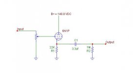
I built the circuit below using the part values indicated in the schematic from an old publication. First of all it works, I measure a B+ of 148.8VDC at the plate to ground of the tube and 4.2VDC from cathode to ground (across 22K).
Can anyone give me the mathematical formula for computing the gain of this circuit?
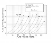
How do I choose the value of the cathode resistor if I will use different tubes? I would like to learn how to effectively use the graphs in tube datasheets for this particular circuit.
Thanks in advance!
JojoD
PS, I know the supply is a bit low but this is an experiment and I don't want to blow things up especially my tubes.
I built the circuit below using the part values indicated in the schematic from an old publication. First of all it works, I measure a B+ of 148.8VDC at the plate to ground of the tube and 4.2VDC from cathode to ground (across 22K).
Can anyone give me the mathematical formula for computing the gain of this circuit?
How do I choose the value of the cathode resistor if I will use different tubes? I would like to learn how to effectively use the graphs in tube datasheets for this particular circuit.
Thanks in advance!
JojoD
PS, I know the supply is a bit low but this is an experiment and I don't want to blow things up especially my tubes.
Attachments
CF
Generally speaking, Cathode Followers have no, or a slight reduction in gain, What they do have is the ability to match up a high impedence source to a lower imp load.
If you need gain, you could precede this stage with a common cathode gain stage using the other half of the 6N1p
Generally speaking, Cathode Followers have no, or a slight reduction in gain, What they do have is the ability to match up a high impedence source to a lower imp load.
If you need gain, you could precede this stage with a common cathode gain stage using the other half of the 6N1p
Re: CF
But how do I choose the cathode resistor for optimum tube performance?
Alastair E said:Generally speaking, Cathode Followers have no, or a slight reduction in gain, What they do have is the ability to match up a high impedence source to a lower imp load.
If you need gain, you could precede this stage with a common cathode gain stage using the other half of the 6N1p
But how do I choose the cathode resistor for optimum tube performance?
s2kov said:JojoD,
You have to determine first your operating point of the tube you will use. By then, you can compute for the value of cathode resistor.
Of course, Ohm's Law will always be here....
Please elaborate. Let's use the 6N1P tube as an example for this exercise.
I don't have datasheet for 6N1P.... But assuming you're using Plate Voltage and Current of 148V and 15mA respectively. Corresponding bias voltage is, say, -6V then you can compute for Rk using this formula:
Rk = Vg/Ia
Where:
Rk = Cathode Resistor
Vg = Grid Voltage
Ia = Plate Current
Please note that above figure is just an assumption, just focus on the above formula base on your operating point that will be used.
Tube Gurus,
Please correct me if i'm wrong....
But assuming you're using Plate Voltage and Current of 148V and 15mA respectively. Corresponding bias voltage is, say, -6V then you can compute for Rk using this formula:Rk = Vg/Ia
Where:
Rk = Cathode Resistor
Vg = Grid Voltage
Ia = Plate Current
Please note that above figure is just an assumption, just focus on the above formula base on your operating point that will be used.
Tube Gurus,
Please correct me if i'm wrong....
JojoD818 said:
Please elaborate. Let's use the 6N1P tube as an example for this exercise.
Something like this?
Given:
300V on plate
bias 15mA
4V / 15mA
Rk = 266R
Try to search for grounded cathode amplifier at www.tubecad.com.
Given:
300V on plate
bias 15mA
4V / 15mA
Rk = 266R
Try to search for grounded cathode amplifier at www.tubecad.com.
s2kov said:Another one:
Plate Voltage = 200V
Plate Current = 10mA
Grid Voltage = -2V
Rk = 2/0.01 = 200R
Hope this help....
This settings would be better, as the maximum anode voltage is 250VDC (from the datasheet)
NB: Running a CF with such a small cathode resistor and such a small cathode voltage is a recipe for high distortion. Before designing a suitable circuit, you have to specify what it is you want it to do. Driver for output tubes? Tape loop buffer? What's the load? How much voltage do you want to swing? Once you've set out the purpose of the circuit, then you can start talking about what's the best topology for it and how to choose the parts values.
Re: You're right
Hi,
Erik and S2kov, It would have been better if we can concentrate on cathode followers only and not discuss other topologies. It makes me confused whether to use your formula or not.
Anyway, the purpose for the circuit is for a buffer without gain. The circuit will drive a 47K load. However, the very reason for my posting is to know how did the original designer came up with 22K as cathode resistor?
JojoD
ErikdeBest said:SY is right. The calculations made through me and S2kv are for a grounded cathode amplifier, and not for a CF (as Jojo18 suggested).
It's good to have the support of the tube gurus. Thank you all.
Erik
Hi,
Erik and S2kov, It would have been better if we can concentrate on cathode followers only and not discuss other topologies. It makes me confused whether to use your formula or not.
Anyway, the purpose for the circuit is for a buffer without gain. The circuit will drive a 47K load. However, the very reason for my posting is to know how did the original designer came up with 22K as cathode resistor?
JojoD
However, the very reason for my posting is to know how did the original designer came up with 22K as cathode resistor?
Assuming you've transcribed this accurately, incompetence would be my first guess.
It would have been better if we can concentrate on cathode followers only and not discuss other topologies.
There are many topologies that fall under the heading "cathode follower." The one you're proposing is not optimum for the intended application; there's no way to get the tube's current up to an appropriate level.
Will this drive a following stage? Or a cable? What are the signal levels you're looking to swing? Bandwidth requirements? Noise? You need to define all of those things before you begin a design.
SY said:
Assuming you've transcribed this accurately, incompetence would be my first guess.
There are many topologies that fall under the heading "cathode follower." The one you're proposing is not optimum for the intended application; there's no way to get the tube's current up to an appropriate level.
Will this drive a following stage? Or a cable? What are the signal levels you're looking to swing? Bandwidth requirements? Noise? You need to define all of those things before you begin a design.
I did follow the publication up to the last resistor value. I can't post the whole paper here due to copyright stuff.
Ok, so using that 22K cathode resistor for that circuit is an incompetence in the part of the designer? Those values should have came from some mathematical formulas but instead it's just a guess?
SY,
I have no need to use this circuit, I just want to study it and learn. In my experiment I used it to drive a cable where the amp is on the other end. For my ears it sounded good but it attenuated the signal, so no gain at all.
Thanks
JojoD
Hi,
In that diagram in post #1, is that a //ed 6N1P or just a single section of it?
If not in // try something in the order of 47K for that cathode R.
Any cathode follower will have some insertion loss due to the high levels of feedback employed so not only will you lose a little gain, with the circuit as shown you'll likely also lose some HF bandwidth with any I/C longer than, say 1 m and 150pF.
BTW, didn't we already point you to all the theory on CFs in a previous thread?
Cheers,
In that diagram in post #1, is that a //ed 6N1P or just a single section of it?
If not in // try something in the order of 47K for that cathode R.
In my experiment I used it to drive a cable where the amp is on the other end. For my ears it sounded good but it attenuated the signal, so no gain at all.
Any cathode follower will have some insertion loss due to the high levels of feedback employed so not only will you lose a little gain, with the circuit as shown you'll likely also lose some HF bandwidth with any I/C longer than, say 1 m and 150pF.
BTW, didn't we already point you to all the theory on CFs in a previous thread?
Cheers,
fdegrove said:Hi,
In that diagram in post #1, is that a //ed 6N1P or just a single section of it?
If not in // try something in the order of 47K for that cathode R.
Any cathode follower will have some insertion loss due to the high levels of feedback employed so not only will you lose a little gain, with the circuit as shown you'll likely also lose some HF bandwidth with any I/C longer than, say 1 m and 150pF.
BTW, didn't we already point you to all the theory on CFs in a previous thread?
Cheers,
Hi Frank,
It is not a // 6n1p, only one section of the tube was used.
Actually I experimented changing the cathode resistors with the following values, 10K, 22K, 27K. They all seem to work but I noticed changes in sound too. I will try 47K as soon as I find one.
Stupid me, I thought this circuit was another tube variation worth another thread.

But the good news is I am really learning a lot from it and from all of you guys!
Thanks and Cheers!
JojoD
Any cathode follower will have some insertion loss due to the high levels of feedback employed
It should be noted that with a CF, the greater the feedback, the lower the insertion loss.
I saw some similarly badly-designed CFs in a Glass Audio article; the same problem with starved-current and nonlinear operating points. Every time I see someone pontificate about how terrible CFs are, I always wonder if they're basing their judgements on one of the many bad circuits out there.
Hi,
Hmmm...Think I know which article in GA you're referring to...
The main problem with the basic CF as posted here is that it can't source and sink current so it's essentially only just about O.K. as an impedance transformer, not much more unless perhaps you'd go to extreme measures, not worth the effort I'd think.
With the 6N1P you could make an excellent CF for driving cable, Miller capacitance and lowish Zin by using something along the lines of the WCF, Broskie or SLCF.
You'll be using both sections of the tube at the very least and should hook it up to a well designed PS with about twice as much voltage than you're using now.
A good CF is a blessing for any tube design, trying to do without is akin to looking for problems where there aren't any IMHO.
Cheers,
- Status
- This old topic is closed. If you want to reopen this topic, contact a moderator using the "Report Post" button.
- Home
- Amplifiers
- Tubes / Valves
- cf topology lessons... pls help