Hello I've done a few tube amp projects but by no means an expert in anything. I was given this Edcore transformer which has 900v ct secondary along with 6.3v and 5v ct windings.
I'm looking for projects that can use this transformer, or perhaps a way to safely drop the voltage down for use in any of the lower voltage amp schematics.
I know this is not the normal way to plan a project but I'd like to use what I have on hand as iron is the most costly part in building hi fi amps.
Any and all suggestions will be greatly appreciated.
Full wave with solid state diodes and choke input will give you less than 405 Volts, according to the primary DCR, choke DCR, and current draw.
If you use a rectifier tube, it might give 50V less than that, so less than 355 Volts.
You have the 5V winding for the rectifier tube.
Let us know what you are going to build.
If you use a rectifier tube, it might give 50V less than that, so less than 355 Volts.
You have the 5V winding for the rectifier tube.
Let us know what you are going to build.
Hello I've done a few tube amp projects but by no means an expert in anything. I was given this Edcore transformer which has 900v ct secondary along with 6.3v and 5v ct windings.
I'm looking for projects that can use this transformer, or perhaps a way to safely drop the voltage down for use in any of the lower voltage amp schematics.
I know this is not the normal way to plan a project but I'd like to use what I have on hand as iron is the most costly part in building hi fi amps.
Any and all suggestions will be greatly appreciated.
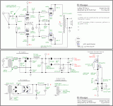
Choke I/P filtration allows access to the full RMS current capability of the power trafo as B+, while yielding a a rail voltage approx. 0.9X the RMS value, less losses. Feeding a "potato masher" 5R4/choke I/P filter combo from the XPWR077 rates to yield a B+ rail suitable for a PP stereoblock using Russian 6Π14Π-EB (6p14p-ev), AKA EL84M, "finals". The 6Π14Π-EB is a genuine 7189 equivalent and 17+ WPC is a reasonable expectation. If a somewhat "taller" B+ rail turns out to be necessary, switching to an ElectroHarmonix (EH) 5U4GB as the rectifier will "do the deed".
There are lots of small signal circuitry options to choose from. However, I suggest "El Cheapo" style in order to retain maximum reserves of B+ current. Current reserves are good for instantaneous extra power, otherwise known as dynamic headroom. TANSTAAFL always applies and dynamic headroom is not a substitute for continuous power capability.
FWIW, Sherwood squeezed an honest 20 WPC out of PP 7189s in their S5000 integrated. HOWEVER, they had a 250 mA. B+ supply and the Edcor power trafo is good for 200 mA. RMS.
Attachments
Last edited:
Hello I've done a few tube amp projects but by no means an expert in anything. I was given this Edcore transformer which has 900v ct secondary along with 6.3v and 5v ct windings.
I'm looking for projects that can use this transformer, or perhaps a way to safely drop the voltage down for use in any of the lower voltage amp schematics.
I know this is not the normal way to plan a project but I'd like to use what I have on hand as iron is the most costly part in building hi fi amps.
Any and all suggestions will be greatly appreciated.
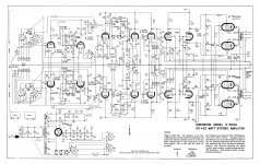
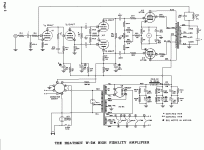
That is the perfect transformer for a 25 watt Williamson with KT66s or 6L6s, The spec on that trafo os very close to what the Heath W5m uses and it's one of my favorite amps for bandwidth and low distortion. A choke IP would sever it well if you want to go that way. Now,you don't need to use series connected lytics as shown here. I now use film caps in the powersupply which they have all the way to 1200v from mouser.
Attachments
Carefully pay attention to the current requirements of any design that draws your interest. It would have been nice if Edcor provided a V/A number for the power trafo. We have to (for safety's sake) assume the 200 mA. number is RMS current. However, it could be a cap. I/P filter number and more current would be available in a choke I/P filtered PSU.
Contacting Edcor for additional info. is (IMO) a very good idea. Not overtaxing a costly part strikes me as being quite sensible.
Contacting Edcor for additional info. is (IMO) a very good idea. Not overtaxing a costly part strikes me as being quite sensible.
It would have been nice if Edcor provided a V/A number for the power trafo.
I agree completely. In conversation over the Edcor forum with Brian Weston, it was my understanding that their transformer current spec is for continuous operation of the entire secondary winding.
Here is a link to the thread.
A bridge across the whole secondary and a 50mA DC load has one particular secondary wire heating effect. 2 diodes and the same secondary, but with center tapped full wave rectification, and the same 50mA DC load has a different secondary wire heating effect. In the first case, the whole winding is used 100% of the time. In the second case, only 1/2 of the winding is used 50% of the time, and the other 1/2 of the winding is used 50% of the time. But of course you get 2x the voltage in the first case than you do in the second case (and 2 times of the DC watts in the first case, versus the second case).
Last edited:
Looks like a simple calculation to see it's 180W. 900 x .200, or 2 x 450 x .200. 180W both ways. If you want to hook it up to draw less through it, that's the designer's option. 180W plus the heater winding ratings..... just to give you the fuse size for the primary.
Last edited:
The point about inductor cost is valid. Up till now, we've focused on power amps and the need to squeeze every last mA. out of the PSU. If a preamp project is considered, lower cost cap. I/P, with its reduced current capability, comes into the picture.
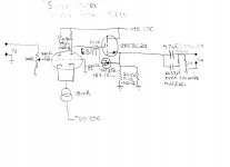
Constructing a 100+ mA. rail from the Edcor trafo is easy enough. Regulating the rail to 475 V. is also not difficult. So, the hybrid line stage I'm uploading becomes feasible. Increase the net source follower load resistance to avoid overloading the B+ PSU.
Constructing a 100+ mA. rail from the Edcor trafo is easy enough. Regulating the rail to 475 V. is also not difficult. So, the hybrid line stage I'm uploading becomes feasible. Increase the net source follower load resistance to avoid overloading the B+ PSU.
Attachments
As long as we are talking about the VA rating, it should be noted that the Watts is not the same as the VA.
Watts = (Cosine of the Phase angle) * VA
Watts will usually be Less than the VA.
For a resistive load, the Phase Angle is Zero Degrees; the Cosine is 1 (i.e. the filaments are resistive). For a reactive load, the Phase Angle is More than Zero Degrees, the Cosine is Less than 1 (i.e. cap input, or choke input).
Where do some of the watts go for a given transformer:
More watts goes to heat the power transformer with a cap input supply. We have Less Current capability but More Volts.
Less watts goes to heat the power transformer with a choke input supply (yes, a little of the heating goes to the choke). We have More Current capability but Less Volts.
The same power transformer can be used for More Current, or for More Volts, but not for both at the same time.
Last edited:
Looks like a simple calculation to see it's 180W. 900 x .200, or 2 x 450 x .200. 180W both ways. If you want to hook it up to draw less through it, that's the designer's option. 180W plus the heater winding ratings..... just to give you the fuse size for the primary.
Hindsight is 20-20 (couldn't resist). easy once you have confirmed that the 200mA spec is for the entire secondary 100% of the time. The point is, that was never a given before the forum discussion with Brian Weston. Compare the Edcor spec with Hammond and see if you get the same result.
We have More Current capability but Less Volts.
The same power transformer can be used for More Current, or for More Volts, but not for both at the same time.
When the specs for current are quoted, that rating should not be exceeded by the load. Wire size of the winding and heat transfer set the limit for ampacity. You cannot safely double the amperage sent through the winding by dropping the voltage by half and doubling the load. If the ampacity of the wire is 200mA, that's what you have to respect as a limit in the design specs. So a VA rating is really meaningless since it suggests no limit to current. Can a 120VA rating be 1v x 120A?
Last edited:
So a VA rating is really meaningless since it suggests no limit to current.
Just like any information: meaningless only if you don't know what to do with it.
The current through the transformer is very different depending on if it feeds, for instance, a bridge rectifier, full wave, half wave, capacitor load, choke input and/or combination thereof, before feeding the actual load. For the transformer not to burn up, its VA rating should not be exceeded. I'd say that's pretty important if you are trying to design a power supply correctly. Ever seen this document?
Ever seen this document?
Did you link to the correct document? Nothing relavant there that would make a point about a VA marking. Does the tranny maker know what you indend to do with the it? It's all RMS specs unless noted otherwise.
Take a transformer with a single primary and a single secondary that has a VA rating of 200VA.
If the secondary rating is 100V then it can do 2 Amps (100V * 2A = 200VA).
But be careful, you can not load the transformer with 4 Amps, because the voltage will not go down to 50V, instead the wires will smoke. Instead, eventually the voltage will go to zero.
(And yes, the link provided by pblix is correct)
This is the link again if your browser could not read the one in post # 18:
Design Guide For Rectifier Use - Hammond Mfg.
Last edited:
- Status
- This old topic is closed. If you want to reopen this topic, contact a moderator using the "Report Post" button.
- Home
- Amplifiers
- Power Supplies
- Suggestions for Edcore XPWR0077