I noticed an interesting effect when simulating a 12AX7 cathodyne (application does not directly drive the output tubes). Running at about 0.7mA using a 100k grid leak for the self bias the outputs are out of balance by about 4%. Switching to a 680k grid leak drops the imbalance to only 0.5%. Apparently there is a grid current issue which imbalances the phase currents if grid leak resistor is too small. Presumably a stage running at higher current would be less sensitive to this but worth keeping in mind.
Don't think I'd use an AX7 for a PI or a 100K GL for it. Kind of a waste.
I wouldn't either if it were driving an output tube (esp triode) grid. Feeding a driver however won't require particularly low Zout or drive current. As to the GL, yes that was a mistake to use such a small value but it did provide an opportunity for learning.
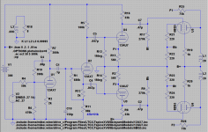
") The particular application calls for keeping size on the small side and using the most common of tubes possible. So we want to avoid using excess current to keep PT size in line. AX7 can be pretty linear at low current so using one triode for a VAS with plate to grid FB and the other for the cathodyne fits the bill. Instead of GNF the output stage will use FB from the plate to the driver cathode. so the PI will have an easy load without a lot of Miller to drive.
The particular application calls for keeping size on the small side and using the most common of tubes possible. So we want to avoid using excess current to keep PT size in line. AX7 can be pretty linear at low current so using one triode for a VAS with plate to grid FB and the other for the cathodyne fits the bill. Instead of GNF the output stage will use FB from the plate to the driver cathode. so the PI will have an easy load without a lot of Miller to drive.Intended layout is 12AX7 VAS ==>12AX7 PI ==> 12AU7 Driver ==> EL84 outputs
Again something like a 6N1P or 6CG7 would make a better driver but the ubiquitous 12AU7 should have no trouble driving an EL84 which is a pretty easy load and the output stage to driver FB loop should tame the HD2 nicely I think.
Last edited:
two quick questions.
1. There was a member that was mentioned here as being a proponent of output plate to driver cathode feedback but I can't remember the user name. I believe that he changed his login name at one point. Does that ring any bells? I am interested in digging out his posts on the topic.
2. With cross coupled (A.K.A. Garter) bias are bypass caps necessary if it is to be a class A amp?
....using a 100k grid leak for the self bias the outputs are out of balance by about 4%. Switching to a 680k grid leak....
And (not mentioned until later) these are 98K cathodyne resistors.
It is reasonable to think that a 100K grid-cathode resistor into a 98K cathode resistor would pass NON-negligible current to the cathode resistor, not reflected in the plate resistor, thus unbalancing stuff.
It is "only" 4% (your number), despite apparently-equal values Rg Rk, because of 12AX7 Mu. That would suggest 2%. I guess the 2K resistor accounts for the other 2%.
If you can't see that, go to extremes. What if this resistor were a short?
When using a 12AX7 for almost any purpose you need to ensure that the cathode-anode voltage is high enough to allow the cathode-grid voltage to be sufficiently negative to avoid grid current. This varies from sample to sample, but never design for less than -1V on the grid.
However, I am not convinced that grid current is the issue here. It could simply be that the 100k grid resistor (in conjunction with the 100k ish output impedance of the first stage) loads the 98k creating direct imbalance.
However, I am not convinced that grid current is the issue here. It could simply be that the 100k grid resistor (in conjunction with the 100k ish output impedance of the first stage) loads the 98k creating direct imbalance.
Yes I see it is simply the signal at the grid "bleeding" into the cathode circuit. Should have been obvious I suppose. In this particular application the driver gain means that the PI won't have to swing much voltage so direct coupling should work fine which eliminates the Rgl entirely. Just need a little larger load resistor on the first stage to get the voltage at a reasonable level.
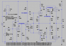
The F1/F2 feedback is positive this way. You have to go from anode to opposite driver kathode. Don't forget that there is DC voltage on the feedback resistor, raising the kathode Voltage and reducing the driver current. You often see a blocking/coupling cap there. Long time ago i used a 1M from 6550 anode (500V) to the ECC82/12au7 driver kathodes. Not a lot of feedback but it worked for me.
50V across a 12AX7 is not very much, so watch out for grid current causing distortion at low frequencies. If you have a good valve model you might be able to see this in Spiceworld.
Good catch, thank you. Actually using the AU7 in both positions might be a better plan as it would allow the first stage plate voltage to be lower and would also give more leeway for the PI bias. As I am looking at it the 12AY7 (which is less ubiquitous but still fairly common I think) might be even better.
Is this going to be a full Class A with @ 280-300v B+?
That is the plan.
Last edited:
That is the plan.
I think that high of biasing will set this for Class B. 19v is above the typical for class B fixed bias on the data sheet for 300v B+.
Parafeed813,
"The F1/F2 feedback is positive this way." Did you mean positive feedback, or did you mean this was a positive (good) thing to do?
Shade Negative feedback is from Plate of the output to the plate of the driver.
This thread's circuit works this way: The driver Cathode and driver Plate are In-Phase. The feedback from the output plate to Either the driver plate Or the driver cathode is Negative Feedback. Only the driver grid is out of phase with the driver plate.
Last edited:
To quote myself:Yes I see it is simply the signal at the grid "bleeding" into the cathode circuit. Should have been obvious I suppose. In this particular application the driver gain means that the PI won't have to swing much voltage so direct coupling should work fine which eliminates the Rgl entirely. Just need a little larger load resistor on the first stage to get the voltage at a reasonable level.
What’s more, Rg constitutes an unintended positive feedback path from cathode to grid, so the total amount of negative feedback within the circuit now depends on the source impedance (as explained for the cathode follower in section 7.5). The higher the source impedance, the lower the feedback fraction and therefore the higher the output impedance and distortion. To put it another way, Rg forms a bridge for unwelcome interaction between the previous stage and following stage. Such interaction may ultimately turn out to be minimal, but why suffer it at all? Fixed bias solves this problem with the same number of components.
- Status
- This old topic is closed. If you want to reopen this topic, contact a moderator using the "Report Post" button.
- Home
- Amplifiers
- Tubes / Valves
- Interesting effect of Cathodyne grid resistor