...I wish I could post the equivalent circuit with this blamed potential divider, but I have no means to do so here at the library computer.....
Using no personal tools:
At PartSim and other sites you can sketch a circuit on-line. You can do some work without an account (though it may be best to get one).
I doodled. I drew a box around the snippet (else I might get a mostly-blank page). Then in PartSim I hit "Export". "PNG" is probably good for forum chalk-board.
Personal tool: my browser is custom to open some images in a PaintBox app. Normally (at a library) it would open in another window, or you would be asked to Save..; just remember where you save it.
Then in forum, Reply, Preview/Advanced, you get a Manage Attachments doodad. Select the image and upload it.
Attachments
If I could scan a napkin, which is probably fully possible here, I could just about manage it. Thank you for pointing out some possibilities for posting a circuit- I haven't been able to figure that out on my own.
Gnobuddy, and the poster before that- that, in fact, is the issue. I have an idea of how things work and then a fact comes along and shatters my whole picture, and then I stammer for a while before some new and doubtless wholly incomplete understanding begins to take its place.
Some areas I have developed really effective mental models in, and can leap from theory to action with confidence. It does happen. This electronics area is definitely not that way for me yet!
Thanks again.
I found this one: EasyEDA - Online PCB design & circuit simulator...some possibilities for posting a circuit...
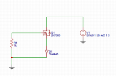
EasyEDA seems reasonably easy to use. I spent a few minutes with it, and drew up the little circuit in the image attached to this post.
The difficulty will be making your own symbols (I didn't see any vacuum tubes included in EasyEDA.) There is probably a way to do that, but for now the simplest solution is to stick a MOSFET where you intend a triode to go...and just add a comment to that effect.
Once you have your schematic in a browser window, you can use any screen-capture software to grab an image from the browser and attach it to a post. I avoid Windows like the plague, but in the past I have used MS Paint and the Print Screen key to grab a screenshot on Windows: How to take a Screenshot in Windows or Mac
If your library is sufficiently enlightened to be using an operating system other than Windows (some use Linux), there will be screen capture programs available for those, too.
My experience is that even when we have good effective models, they collapse when confronted with something entirely new and different. My mother was a good cook, entirely at home in the kitchen, until she encountered her first avocado. She didn't have the slightest idea what to do with it, and in those pre-Internet days, had no way to find out. So she boiled it...Some areas I have developed really effective mental models in, and can leap from theory to action with confidence.
-Gnobuddy
Attachments
Agreed on the limitations of models- always wary of that...
I am wondering about the issue of oscillation in an all-in-one-bottle cascode. I've searched some and am not seeing anything about how to address this.
There's a high frequency oscillation path via Ca-a, and of course the anode of the lower valve feeds the cathode of the upper valve, so we have plenty of loop gain and positive feedback, as this is not an inverting amplifier (from cathode to anode of the upper valve).
I am aware that the ECC88 has an internal shield that reduces Ca-a to .045 pF (from Telefunken datasheet). Another solution would be separate bottles.
I'm wondering what if anything can be done about this issue when using two valves in the same bottle, without an internal shield, in a cascode.
I note that there is a similar path in every triode, Ca-k, that would provide a positive feedback path with gain in most situations. Perhaps this is just not an issue?
I could imagine Ca-k multiplied by the Miller effect when feeding the valve from the cathode, as in the cascode. Perhaps this is not an issue either!
I note that Telefunken has Ca-k down to .2pF in their ECC88. I found a figure for a 12AT7 of .4 or .5 pF.
There's some series resistance (ra of the lower valve) but I don't see that inductance would even need to play a part with all that gain and no inversion.
Thanks!
Uh, that would place Caa in parallel with the internal resistance of the upper valve, which would tend to reduce HF gain, not increase it...There's a high frequency oscillation path via Ca-a, and of course the anode of the lower valve feeds the cathode of the upper valve,
It's certainly possible to intentionally create oscillation by feeding back a signal from the anode to the cathode. But your concern seems to be that this might happen inadvertently through stray capacitance, so let's see if we can put some numbers to this.I note that there is a similar path in every triode, Ca-k, that would provide a positive feedback path with gain in most situations. Perhaps this is just not an issue?
A key factor is the input impedance at the cathode, with the grid grounded (as far as AC goes.) For a triode, the internal impedance at the cathode is (1/gm + ra/mu + Ra/mu). Taking a half-12AX7 as an example, 1/gm is between 600 and 800 ohms, and (ra/mu) is about 700 - 800 ohms. If we assume Ra is 100k, then (Ra/mu) is another 1000 ohms. Adding it all up, the impedance "looking into" the cathode is around 2500 ohms.
If an external cathode resistor Rk is used, that will have to be paralleled with 2500 ohms to find the input resistance at the cathode. In the case of a cascode, the cathode of the upper triode is being fed from the rather high anode impedance of the lower triode, which will have negligible effect on the 2500 ohm input impedance at the cathode of the upper triode.
Now let's suppose that, through truly abysmal layout, we have managed to create a whopping 5 pF of stray capacitance from anode to cathode (about a hundred times more than your figure for the ECC88.)
Let's assume the upper triode has a voltage gain of, say, 50 times from cathode to anode.
To create oscillation by feeding back the anode signal to the cathode, we have to have a loop gain of 1. Since the gain is 50x, at least 1/50th of the output signal needs to get fed to the cathode to cause oscillation.
We have 2500 ohms input impedance at the cathode. Fifty times that is 125 kilo ohms. So if we use a 125k (or less) feedback impedance from anode to cathode, we might just manage to start oscillations. (In reality the 125k feedback impedance would load down the triode and reduce voltage gain, so we would need less than 125k feedback impedance to start oscillations.)
The next question is, at what frequency does our 5pF stray capacitance have an impedance of 125 kilo ohms? That's easily calculated, and the answer is, around 255 kHz.
For audio, the highest frequency that matters is 20 kHz. 255 kHz is nearly 13 times that uppermost frequency.
The solution is trivially simple: make sure your audio amplifier's upper bandwidth doesn't extend out to 255 kHz! Extra HF bandwidth is always a bad idea - it increases noise, susceptibility to interference, and the possibility of unwanted oscillations.
In this case, we might choose to parallel the upper triode's anode load with a small capacitance that rolls off gain above, say, 30 kHz. 47 pF would do the job. (Or, keeping Merlin's advice from his tube guitar preamp book in mind, we could wire that capacitor from the anode of the upper triode to ground, rather than from anode to B+.)
Conclusion: we would have to be doubly stupid to create oscillations via anode-cathode feedback of a triode; first we would have to botch the layout so badly as to create a whopping 5 pF of stray capacitance, then we would have to botch our design process by letting our audio amp have gain out to thirteen times the highest audio frequency.
(At some point in your audio meanderings, you will encounter an audiophile who is convinced that an audio amplifier needs a 3 MHz bandwidth to sound good. When you encounter such a person, I recommend treating him (it's never a "her") the same way you would any other harmless lunatic: nod and smile politely, then walk away, and put the nonsense out of your mind.
") )
)-Gnobuddy
Because there are parasitic capacitances, parasitic inductances, and wire/air transformers, it is hard to predict all possible oscillations that may occur. Experience is the best teacher, but sometimes we get caught with an unexpected oscillation.
There are Colpitts, Hartley, Buttler, Clapp, Pierce, TPTG, Negative Resistance, and many other oscillator types.
Fortunately, we usually do not have gain, feedback, and the correct phase all at the same time for an oscillation to occur. But sometimes we build an amplifier that becomes an oscillator (and sometimes we build an oscillator that becomes an amplifier: I know someone who could never design a Colpitts oscillator that would oscillate). For myself, I loved using a JFET to make a Colpitts oscillator in the 2 to 10 MHz region (A very predictable circuit).
...I note that there is a similar path in every triode, Ca-k, that would provide a positive feedback path with gain in most situations. Perhaps this is just not an issue?...
What is the voltage gain/loss from plate to cathode? Roughly rp/rk. Which is just a different way to say Amplification Factor. Alternatively, what is the Current Gain from cathode to plate? Unity, minus bias losses. The loop gain from plate to cathode is "always"(*) less than unity.
(*) In basic audio systems. A transformer or tuned-circuit can trade voltage for current and reach positive gain; maybe half the RF oscillators do this. I have seen an "audio amplifier" do this, coupling from wire to wire-wound resistor (few-turn transformer), singing >1MHz.
A good place to start is to assume that this 'problem' which you have seen is not addressed by others because it is not a problem.tapehead ted said:I am wondering about the issue of oscillation in an all-in-one-bottle cascode. I've searched some and am not seeing anything about how to address this.
There's a high frequency oscillation path via Ca-a, and of course the anode of the lower valve feeds the cathode of the upper valve, so we have plenty of loop gain and positive feedback, as this is not an inverting amplifier (from cathode to anode of the upper valve).
In this case there is very little loop gain, because the lower anode is connected to the upper cathode and this is a low impedance node. Valves designed for cascode operation often include an internal shield to reduce it still further.
Cathode is low impedance, and in many cases is decoupled too.I note that there is a similar path in every triode, Ca-k, that would provide a positive feedback path with gain in most situations. Perhaps this is just not an issue?
Miller effect here has the opposite sign so you could end up with negative capacitance.I could imagine Ca-k multiplied by the Miller effect when feeding the valve from the cathode, as in the cascode. Perhaps this is not an issue either!
Here are some examples how a parasitic tuned circuit can cause oscillations.
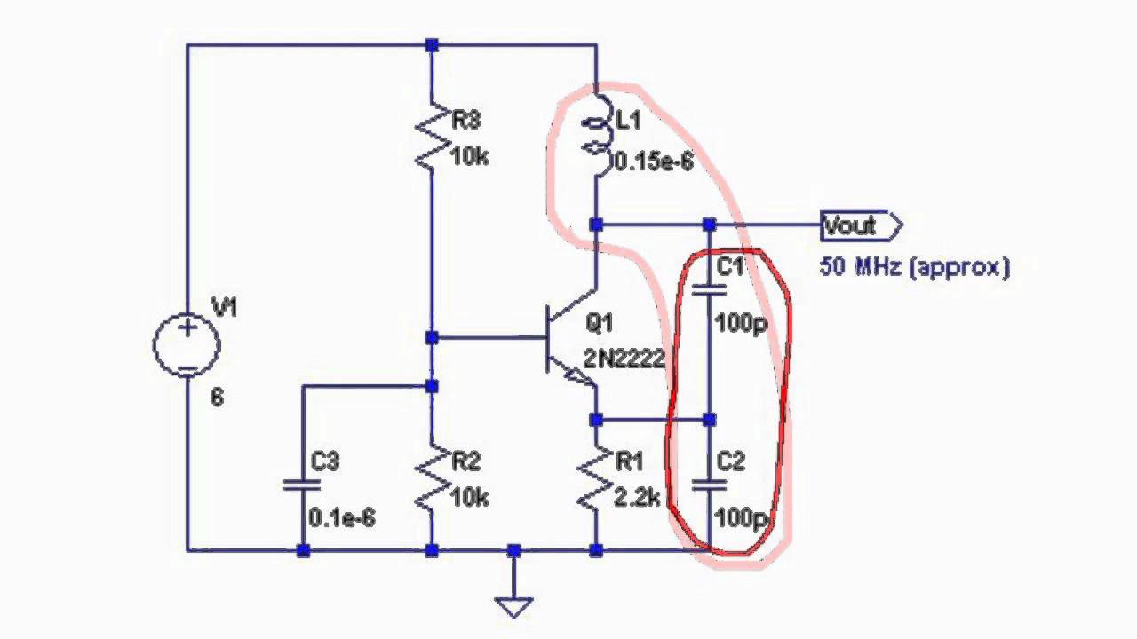
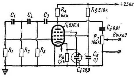
Here is an example of 1-tube oscillator, with phase shift in a negative feedback loop:
Here is an example of 1-tube oscillator, with phase shift in a negative feedback loop:
An externally hosted image should be here but it was not working when we last tested it.
Agreed on the limitations of models- always wary of that...
I am wondering about the issue of oscillation in an all-in-one-bottle cascode. I've searched some and am not seeing anything about how to address this.
!
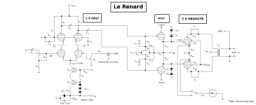
I've done this design, and it's not a problem. The cascode has a lot of the same properties as a pentode: high voltage gain, high plate resistance, small Ci. Use the same precautions: keep all leads as short as possible, use sockets that come with a central metal pin and ground it as directly as possible. Use the upper triode grid bypass capacitor to do double duty as an electrostatic shield. The main advantage the cascode has over a pentode is that there is no "screen" current, so you can use decoupling here to remotely locate the voltage divider. (The schemo was a prelim version, and the actual construction has 1MEG grid resistors with 0.1uF bypasses straight to the ground plane on each upper triode.)
You may get oscillations (I did: a weak one at several MHz) and these can be answered with grid stoppers. Once the stopper was added, no more oscillation.
Attachments
Last edited:
(and sometimes we build an oscillator that becomes an amplifier: I know someone who could never design a Colpitts oscillator that would oscillate). For myself, I loved using a JFET to make a Colpitts oscillator in the 2 to 10 MHz region (A very predictable circuit).
The Colpitts needs a high gain device in order to be implemented decently. BJTs work best for that. It can be done with lower gain devices, but at the expense of tighter coupling between the LC tuner and the active device which negatively impacts the frequency stability.
I built JFET Colpitts oscillators.
You use a very high Q, very low inductance coil. Then you use 2 capacitors in series to divide the power off the coil. The very low L and very high C has the feature that the two capacitors swamp out the JFETs capacitance. It makes it less susceptible to drift with temperature and with power supply variations.
A 9V Battery, bypass cap, coil, JFET, 2 silver mica caps, and a resistor are all that are needed. 7 parts. You can not get much simpler than that.
I used them in Ultrasound Dopplers.
I also used them in a short wave down convertor.
A light coupling from the capacitive divider to the 'outside world' kept the intrinsic stability intact.
All the statements above are relative.
A 9V Battery, bypass cap, coil, JFET, 2 silver mica caps, and a resistor are all that are needed. 7 parts. You can not get much simpler than that.
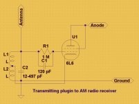
We used even less when were kids.
However, it was illegal. But 4 wires under an output tube of any radio receiver were turning it into an AM transmitter. Well, antenna switch and a microphone were needed. Sometimes carbon microphones were used, so one more resistor to power it was going to cathode of an output tube.
Attachments
Thank you all so much, I really do appreciate it. FWIW, I am never certain what is taken into account by the knowledgeable.
Are these additional grid stoppers on the upper grids? I'm thinking they would have to be small enough compared to the reactance of the upper grid decoupling caps not to interfere. I've wondered about that.You may get oscillations (I did: a weak one at several MHz) and these can be answered with grid stoppers. Once the stopper was added, no more oscillation.
Are these additional grid stoppers on the upper grids? I'm thinking they would have to be small enough compared to the reactance of the upper grid decoupling caps not to interfere. I've wondered about that.
Definitely not. The cascode is a two stage amp: grounded cathode --> grounded grid. The upper triode is a GG, and you want to keep impedance out of the grid connection as much as possible by either a direct connection or a stiff bypass capacitor if that's not possible. impedance between the grid and ground will promote instability. This is why the grounded base is less stable than the vacuum tube grounded grid: that irreducible rb. Or why 811A GG power amps sometimes require neutralization, especially at the higher frequency SW bands: internally, there's a couple of inches of wire between the grid and ground.
- Status
- This old topic is closed. If you want to reopen this topic, contact a moderator using the "Report Post" button.
- Home
- Amplifiers
- Tubes / Valves
- Miller Capacitance