Finally broke out my Tubecad CCDA PCB, after a few years, to use for a project. Already had most of the parts soldered on except C1, the coupling caps. I have a few in the right size, (voltage and capacitance), but soldering and unsoldering various coupling caps could pull up a pad. Would it be a bad idea to solder two, stiff, upright leads to the C1 pads, circled in red, so I can solder on different caps? Or should I just pick a pair and move on.
Attachments
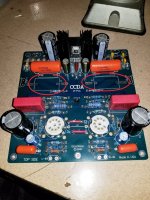
Would it be a bad idea to solder two, stiff, upright leads to the C1 pads
Try get a strip of "Single Row Socket Connector Strip". Cut out a couple of single pin. You can use it as a capacitor socket. When you are done, solder the capacitor to the pin to get rid of whatever inductance or resistance that it introduced.
Would it be a bad idea to solder two, stiff, upright leads to the C1 pads.
Yes, I would use the pieces of wire as tie points for testing. Use pads that you
won't end up using long term, and just cut off the test wires when finished.
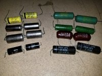
I don't think you are going to like most of those capacitors, so you'll probably
want to remove most of them after a short time.
Thanks guys. Rayma, if you had to pick a pair?
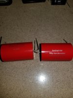
I would only try the Solen and the Russian capacitors.
The paper and polyester caps won't fare very well.
The black cats also often develop significant leakage.
Last edited:
- Status
- This old topic is closed. If you want to reopen this topic, contact a moderator using the "Report Post" button.
- Home
- Amplifiers
- Tubes / Valves
- Tubecad CCDA PCB