The correct bus order is secondary CT - reservoir -ve - smoother -ve etc. - amplifier ground. The idea is to keep charging pulses well away from everything else.Diyengineer said:Would you be able to give me a quick explanation with details of how you might ground this amplifier?
http://www.valvewizard.co.uk/Grounding.pdf
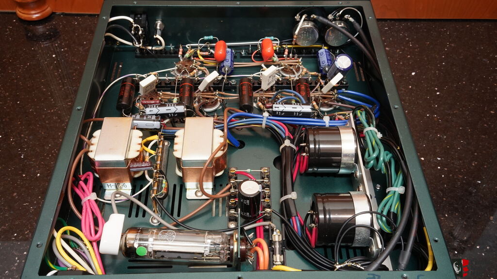
in amp famous brands ...ground is key of product . if dont use pcb can test until find best point .
in picture we can see bad grund
.
in amp famous brands ...ground is key of product . if dont use pcb can test until find best point .
in picture we can see bad grund
.
The correct bus order is secondary CT - reservoir -ve - smoother -ve etc. - amplifier ground. The idea is to keep charging pulses well away from everything else.
Would you also ground the filament C.T. to the same location as the HV C.T.?
Right now, both are to the bottom of the filter caps.
Thanks
An externally hosted image should be here but it was not working when we last tested it.
grund system used by shindo labs in japan .be careful at black wires .i used this grand system more times .
this is not from iran so you can use method of gerund in picture !!!!!!!!!
Last edited:
Heater CT should be grounded to amplifier ground or smoothing cap ground. Definitely not high voltage secondary CT, as that carries charging pulses.Diyengineer said:Would you also ground the filament C.T. to the same location as the HV C.T.?
The idea is to make a circuit that has current only from the HV secondary, diodes, and 1st capacitor (and 2nd capacitor when there is only a small resistor between the 1st and 2nd caps), and the rest of the HV circuit (the return from the bottom of the 2 capacitors to the center tap). This circuit has to be a stand alone, with its own return wire(s) to the center tap; all the charging current is local to the HV supply. Once you have that closed loop circuit, then the negative end of the 1st capacitor has a wire to the "outside world" (the rest of the amplifier's "central ground").
An example of what Not to do is use 3 wires to amplifier central ground: connecting the center tap with a wire to central ground, 1st cap negative lead with a wire to central ground, 2nd cap negative lead with a wire to central ground.
I have 3-wire power outlets and 3-wire IEC power cords, and 3-wire IEC power inlets on all my power amplifiers. I connect the IEC power input connector ground directly with a short wire to a ground lug on the chassis at that power input connector (safety). I connect another ground lug to the chassis, typically at the center of the amplifier (what am calling "central ground"). I mount the RCA phono input connector with insulating washers, and connect the RCA phono input connector return-lug with a wire to "central ground". (the RCA phono connector is the power amp line level input; it is not a phono cartridge input).
The output transformer secondary Common wire is connected to the "central ground" (safety).
All the other power amplifier circuitry return circuits are connected to the "central ground" (input tube self bias return, grid return resistor, LTP current source negative volts supply return (+ lead), output tube self bias return, etc.).
All my other Hi Fi equipment have 2-wire power plugs, stock from the factory (and remain stock, no modifications). CD player, AM/FM tuner, Turntable, Phono Preamp. I connect the Turntable ground wire to the dedicated ground-screw on the phono preamp. The only other 'ground' connections are with RCA phono plugs connecting signal outputs to input signal selector switch, and to the remote controlled passive volume control. But the only connection to power outlet ground is at/to the power amplifier.
My power amplifiers do not use negative feedback, and do not use regulated supplies, and do not use DC for filaments except for Direct Heated Triodes that I have on some amplifiers (most are not DHT amplifiers). The hum is lower than 500uV, with some less than 100uV. It is not the only way to do it, but it works for me.
Last edited:
Summer,
after reading your last post through, I need to rework a couple things. I’ll let you know if it changes anything.
I re-grounded per your method described above. While I’m sure it is grounded a much better way, the buzz it still the same over the loudspeaker.
I’m hoping the choke will take care of it. Hopefully I’ll have it before the weekend.
Just a thought, and not sure if is even possible with this circuit or if it would even make a difference, but would using the 40% ultra linear taps to power the screens offer any benefit? Rather than using the screen supply.
Not sure if using them could possibly solve the buzz issue.
Thanks!
Here are a few generalizations:
I doubt that using Ultra Linear mode would reduce the hum in the loudspeakers. I doubt that using Ultra Linear mode would reduce the mechanical buzz.
Your amp schematic shows global negative feedback, and lots of gain in the stages. The global negative feedback dictates the overall gain from input to output. It also reduces the output impedance (higher damping factor) and reduces distortion.
Connecting the screens to the UL taps reduces the gain of the output stage (versus Pentode mode). UL is local negative feedback that reduces the plate resistance of the output stage, and reduces the distortion (versus Pentode mode). But the overall gain from input to output is almost certainly still dictated by the negative feedback, and the output impedance and distortion will remain about the same (because when you reduce the gain of the output stage, the ratio of the amplifier gain without feedback versus with feedback is reduced). The quiescent plate current and quiescent screen current will be about the same as in Pentode mode. UL has about the same power out as Pentode mode.
Triode wired mode further reduces the output stage gain, and further reduces the output stage plate resistance, and the distortion.
Pentode mode is very high gain, and very high output impedance, and has more distortion which is why global negative feedback is usually used with pentode mode outputs.
Triode wired mode has low gain, low distortion, and low output impedance, which is why global negative feedback is often not used. It also has less power out.
UL mode output stage has about 2 times the gain, about 2 times the output impedance, and higher distortion versus triode mode, which is why global negative feedback is often used.
"All generalizations have exceptions"
Last edited:
Alan4411,
Thanks! You were right! That Hammond chart about DC output current gave the right data.
I was incorrectly thinking about a Bridge rectifier with capacitor input filter (like DC filaments I have used for DHT amps). All the secondary is used all the time.
Of course a full wave rectifier with center tap and capacitor input filter does have more DC output current from a given transformer current rating. Only 1/2 of the secondary is used at a time, first one half, then the other half.
The 200mA Hammond center tapped secondary should be able to easily power the 150mA DC load of the amplifier.
Diyengineer, ''...would using the 40% ultra linear taps to power the screens offer any benefit?'' - unlikely as you have tried 'triode' mode already.
There is lots of excellent advice being given on this thread, but you have 2 problems. Mechanical buzz and a buzz from the speakers.
You have to fault find them as two different faults.
I think you have proved the mechanical buzz is load related. Some transformers do buzz - a fact of life. The choke input hopefully might work, if not physical isolation from the chassis is the next step etc.
The speaker buzz or hum, is another can of worms. Poor grounding, poor heater wiring, insufficient decoupling between stages and so on...
As was mentioned by Hooman in #65 best place to start is by removing the valve/tubes from each stage at a time and listening. Take out the EF86, if the hum goes fault find the associated area, if not pull the phase splitter out, same again, if the hum disappears fault find that stage. And so on. If you have hum from the speakers with the 4 x KT66s removed that will be an interesting fault...
Pictures again could help.
Alan
I once had an amplifier that had a little hum you could hear in the speakers before the tubes were warmed up.
Even if you removed the output tubes, you could still hear it in the speakers.
The problem was caused by the power transformer that had the output transformers on either side (and much too close). The magnetic coupling created the hum.
When the amp was warmed up, the amp damping factor shunted out the small signal that was caused by the magnetic coupling.
A filter choke that is too near to an output transformer could also cause the problem. Many times you do not have enough space between the output transformer versus the choke or power transformer. That is why it is important to mount them at right angles to each other.
Last edited:
Agreed. When I use EI transformers I group the power transformers and choke on one end of the chassis, and the OPTs on the other, with the power tubes closest to the power transformers, and the input/phase splitter nearest the OPTs. They aren't 90 degrees but they are 12" apart.
Hello all,
So I tried the choke tonight. Basically it’s the opposite of what I thought would happen. The mechanical buzz got slightly louder and the tone of the buzz for slightly deeper. The buzz over the speaker nearly disappeared which I really wasn’t expecting.
The buzz on the speaker didn’t outweigh the new louder mechanical buzz so I reverted back to the cap input filter. I didn’t bother re-biasing the amp because I went back to the caps for now.
All of the voltages were quite a bit lower. The plate voltage was cut by 130v. The cathode current went from 70mA to 42.5mA. Surprisingly the amp still sounded very good. I played it side by side with the other monoblock and couldn’t really hear a difference in level of volume. The tone was slightly different but not by much.
Might just have to get a bigger transformer.
Let me know if there’s anything else I should try with the choke.
Thanks
Is the chassis magnetic (iron)?
Does the the power transformer have some iron lid around it?
One local audiophile once brought me a boutique amp that was buzzing.
I made a copper band around the power transformer, and the buzz become less loud, but the iron lid that covered it still was buzzing. It was such a buzzing design.
Does the the power transformer have some iron lid around it?
One local audiophile once brought me a boutique amp that was buzzing.
I made a copper band around the power transformer, and the buzz become less loud, but the iron lid that covered it still was buzzing. It was such a buzzing design.
Diyengineer, I know 6A3s will be along shortly, but a couple of things to ask.
The increased buzzing - was it from the transformer still or the new choke?
That position is hard work for a choke, it has raw dc (half ac waveform) on it and that makes the choke 'sing' unless very well bolted down and clamped. Also it has a very large magnetic field, so is even more critical as to orientation and spacing from the other transformers and chokes...
If it is from the transformer still, try and add a 0.22uF or 0.1uF 1000 volt poly cap at the front of the choke where the rectifiers join, to ground. Another thing that raw dc does is cause a 'flyback' voltage due to the field collapsing nearly to zero. That flyback voltage sends pulses back to the transformer. Adding a small cap quenches the flyback by holding the waveform off zero and minimises the pulses.
Alan
Last edited:
Diyengineer,
I believe the choke you ordered was the same choke that I use, a Hammond "Reactor 193H", 5H 200mA. That should work.
I never heard one of that model of choke hum, but if it was not made correctly, it might.
Did it look like it was dropped?
As Alan said, was the choke humming? It would on a magnetic chassis.
The choke should have reduced the B+ ripple (and it seems it did, because there was less hum in the loudspeakers).
If the 5H choke was connected Between the diodes (nothing else connected to the diodes) and the other end of the choke connected to the first filter cap, it should have reduced the transient current on the power transformer secondary.
Normally, I would expect that to make the power transformer buzz less.
Did you ever find if the stainless steel was magnetic, or non-magnetic?
As Alan said, you could use a small capacitance 1000V capacitor. But use 1uF. The problem with a 0.22uF is that it resonates with 5H at about 152Hz, way to close to the frequency of the full wave rectifier (120Hz). And if the actual inductance is just a little more than 5H, it will resonate even closer to 120Hz.
Were the power transformers dropped, or were the end bells pulled off and remounted, or other disturbance of the transformer change the mechanical integrity of them?
Other than that, at this point I am running out of ideas.
Last edited:
- Status
- This old topic is closed. If you want to reopen this topic, contact a moderator using the "Report Post" button.
- Home
- Amplifiers
- Tubes / Valves
- Reducing gain in a monoblock