Hi Folks,
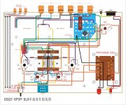
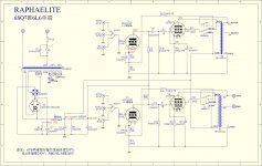
I bought a Raphaelite DSK6L 6L6 GC single-ended amp second hand and the documentation *I think* shows the heaters to be wired in series but the amp I have seems to be in parallel, via 2 sets of 6.3V taps from the transformer.
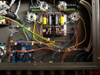
I found the first pic and diagram online and my unit is the last pic.
Which is correct?
Appreciate any help forthcoming here")
Many thanks!
I bought a Raphaelite DSK6L 6L6 GC single-ended amp second hand and the documentation *I think* shows the heaters to be wired in series but the amp I have seems to be in parallel, via 2 sets of 6.3V taps from the transformer.
I found the first pic and diagram online and my unit is the last pic.
Which is correct?
Appreciate any help forthcoming here
Many thanks!
Attachments
No problem, hope this helps.
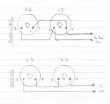
Use V3 and V4 as the example. (V1 and 2 are the same, but different pin numbers.)
Parallel connected.
Two ways to do it, first like your amp, feed each valve individually from the transformer 6.3v winding. Or like the 'schematic' take one pair of wires from the transformer to V3 pins 2 and 7. Then feed V4 from those by linking both their pins 2 and 7 together. Either way they are paralleled and both methods have 8 connections in total.
Series connected.
One wire from the transformer (6.3v) goes to V3 pin 7. V3 pin 2 is now connected to V4 pin 7. And V4 pin 2 connects back to the transformer 6.3v connection. If you look there is only one connection at each location so 6 in total.
The sketch tries to show the un-twisted schematic version, parallel, and what it would be if it was 'series' connected.
Alan
Attachments
Almost all PP type amps use parallel heater wire connections. Sometimes there are 2 or more filament circuits. 1 for the power tubes and 1 for the preamp tubes. There is also different ways to make the connections but the end result would still be the same. If all the heaters measure at 6.3 more or less i would not worry about it. Unless, you are having a problem with hum from the heater lines?
....I presume this is correct, they should be grounded to the chassis? ...
Yes.
A) User safety. If the transformer insulation failed, 400V wants to go to the exposed speaker terminals and the user messing with them. A grounded secondary will limit the voltage to almost-none, and typically something else will burn-up quick, removing danger.
B) The amp appears to have NFB. There are green wires from secondary to a switch to a resistor network, probably under the first cathode. This won't work unless the other side of the secondary is also referenced. The drawing shows a black wire from both zero terminals to the power board and from there to the heart of the amplifier. There are several ways this could have been done, and your build may do it different in mechanical detail, but same intent.
Also: To ground or not to ground the OPT secondary, that is the question
Last edited:
Yes.
A) User safety.
Thank you PRR. This is my priority of course
Just a noob question if I may...
The switch is labelled Triode / Pentode. Difference?
> The switch is labelled Triode / Pentode. Difference?
I was gone blind working out that wire-diagram.
OK, NFB is disconnected in triode, connected in pentode. Naked (no NFB) triodes are quite listenable, naked pentodes are awful brash/bright/barky and want NFB.
Since you might use it in pentode w/NFB, and anyway need the ground for safety, they just ground it.
> The switch is labelled Triode / Pentode. Difference?
I was gone blind working out that wire-diagram.
OK, NFB is disconnected in triode, connected in pentode. Naked (no NFB) triodes are quite listenable, naked pentodes are awful brash/bright/barky and want NFB.
Since you might use it in pentode w/NFB, and anyway need the ground for safety, they just ground it.
Thank you very much for the explanation.
If in fact I do prefer SET as opposed to SEP then can I easily remove the switch and associated wiring? I'm a firm believer in "less is more" but I'm also very conscious of safety and under no illusions re my understanding of such circuits.
On another note I did get the chance to check both 6.3V windings and I was very happy to measure 6.32V on both!
Thanks to all for all the good advice.
- Status
- This old topic is closed. If you want to reopen this topic, contact a moderator using the "Report Post" button.
- Home
- Amplifiers
- Tubes / Valves
- Heaters wired in parallel?