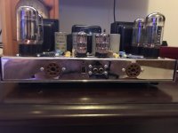
Just purchased this ST-70 with a GSI mod as an introduction to tube amps. Limited (none) experience with tube amps and wiring but figured needed to start somewhere. Sadly I can’t even figure out how to set bias because I can’t locate the bias pots nor can I identify the bias set point. Any help would be much appreciated. Amp sounds great.
Attachments
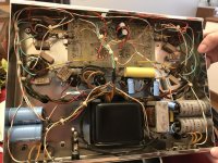

On top of the board there are two white trimmer ( I see) , is it correct?
About the bias if you have a tester, you cam take off the output tubes and check the pin 1 and 8 to ground, in this way you can read the value of cathode resistor, in a picture I read 10 ohms.
You need about 35mA of bias so you must read 350 mV on each 10 ohm resistors.
Walter
About the bias if you have a tester, you cam take off the output tubes and check the pin 1 and 8 to ground, in this way you can read the value of cathode resistor, in a picture I read 10 ohms.
You need about 35mA of bias so you must read 350 mV on each 10 ohm resistors.
Walter
GSI was Andy Fuchs - Yonkers NY. A Harvey Rosenberg "spinoff" - believe the original company had a different name. Had a few iterations of the input board ending up with a cascode-differential circuit a la Hedge from the 50's. That circuit out-performed the original and any of the other "competitor" boards I tried. Will look for the schematic.
Charles
Charles
From the research I have done it does appear that GSI was associated with Andy Fuchs. Supposedly, the G in GSI stood for gizmo. I like the unusual back story and build. The Amp was modified in 1987 according to a label on the cage. There is some documentation with the amp which does include a possible schematic. That documentation appears to be a brochure for services potentially non-specific to the amp I have. Will post further pictures when I get off work in about 12 hours.
Thanks for all the help. I suspected that the adjustment pots might be the white devices on the board but all of the material I could find online on the ST-70 showed large mechanical potentiometers. Can I assume that bias adjustment would be the same procedure with these pots as shown with the traditional ST-70 pots? Advice on good reference material for a novice to read would also be appreciated.
Thanks for all the help. I suspected that the adjustment pots might be the white devices on the board but all of the material I could find online on the ST-70 showed large mechanical potentiometers. Can I assume that bias adjustment would be the same procedure with these pots as shown with the traditional ST-70 pots? Advice on good reference material for a novice to read would also be appreciated.
I think that the this amp is different for checking the bias.
In this case is simple because there are one 10 ohm resistor for each power tube.
With a little experience you can set at the best the bias.
Without the power tube inserted you can check the voltage on pin 5 of each socket of the power tube to verify that turning the white trimmer the neg. voltage will change; in this case is better to set at around -40 vdc for each tube.
Walter
It's a good sounding design as Charles has indicated and far better than the stock ST-70 ever was.
Andy and I were friends, but I've long since lost touch with him.
GSI to the best of my recollection stood for Gnome Sound Incorporated. I am not aware of any direct connection with Harvey Rosenberg, but it's not unlikely given how influential Rosenberg was in those days to east coast tube aficionados..
IIRC there would be 4 pots located 1 each at the corners of the board nearest the respective output tube which set the bias. The stock operating point of the amplifier would be around 50mA per tube (500mV across a 10 ohm cathode resistor). Somewhat lower current will not compromise performance too much and will result in longer tube life.
So if I am understanding this correctly I am setting the bias to .5 volts while checking pin 8 of each socket on the board with the tube removed and grounding the meter to the frame of the amp. If this is correct I am a bit confused because all the amp bias setting information I have read set the bias with the tube in operation and it seemed that the tube was an important part of the bias setting process.
Maybe my question is stated incorrectly and I should be setting both amp voltage and tube bias?
Maybe my question is stated incorrectly and I should be setting both amp voltage and tube bias?
This is the beauty with a well documented and good design like the original dynaco. "Connect a voltmeter between the biaset and ground and turn the biasSo if I am understanding this correctly I am setting the bias to .5 volts while checking pin 8 of each socket on the board with the tube removed and grounding the meter to the frame of the amp. If this is correct I am a bit confused because all the amp bias setting information I have read set the bias with the tube in operation and it seemed that the tube was an important part of the bias setting process.
Maybe my question is stated incorrectly and I should be setting both amp voltage and tube bias?
adjustment until 1.56Volt is read." All described with all tubes in place and the amp warmed up but no signal. Clearly marked measuring points are even
present at the front of the amp, no need to poke around inside.
The GSI above has a 10 ohm resistor between ground and each cathode. One should measure across these resistors with all tubes in place and amp warmed up, then adjustment is turned for each tube untill they all reads 0.5Volt.
This is why it's so important with schematics and good (correct) documentation, especially for the beginners. Mistakes here might cause damage and be expensive to repair.
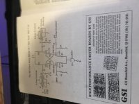
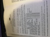
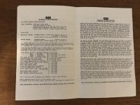
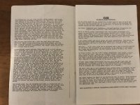
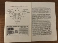
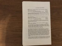
Attached you will find the GSI materials that came with the Amp. The first attachment contains a schematic and board description. The other pages describe mod options and work details and if anyone is interested in the whole document would be happy to attach the other 6 pages. Love the fact that the 8417 tubes cost $13 back then.
Attachments
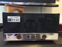
Here are all the pages. Tried to do a better job on the images. Any idea where the bias set points would be located on this amp? It looks to me like the orange, green, white wires may lead to a bias set points on the outside of the chassis. Don’t have much access to professional stereo tube amp techs where I live but going to hit a few places that seem to be more guitar amp guys. Having difficulty uploading so will try doing it in 2 posts b
Attachments
Very simple: Use the trimmers for each power tube, to set for the current you desire. 300 mv dc equals 30 ma, and so forth. Use a quality digital Dc voltmeter set to voltage not current. The trimmers will affect one another, so set them in order and go back to the first trimmer, until all tubes are at desired current.
FWIW: I still support and service these units. I've even built a few mods for customers wanting them. It is truly miles ahead of the stock circuit with 7199's. Besides the fact you cannot find decent 7199's anymore that circuit wasn't the best circuit by modern audiophile standards.
I currently own and operate a company manufacturing tube guitar amps and also operate a service facility for musical and sound reinforcement equipment.
Fuchs Audio Technology
Thanks for all the responses. The tube community lives up to it's reputation as a knowledgeable and helpful group. Unfortunately, this discussion has shown the depths of my ignorance on the subject matter which can probably only be rectified by signing up for a few classes on electronics at the local university. My father once punished me for messing around with our tube TV. As a machinist he had very heavy hands and left me with a healthy respect for the dangers to both the unit and my person. Mr. Fuchs thanks for your kind response and I can see a rebuild being in my future. The unit still sounds great and looks great by the way. I did start it up slowly with a variac when I first powered it up and continue to power it through a variac.
The stock ST-70 has a clearly defined bias set point identified on the outside front of the unit. I suspect that perhaps this mod also has a similar feature? Of course there would need to be 4 bias set points. Even with the instruction so far in this thread I an uncertain as to where I take the measurements.
"The GSI above has a 10 ohm resistor between ground and each cathode. One should measure across these resistors with all tubes in place and amp warmed up, then adjustment is turned for each tube until they all reads 0.5Volt."
I understand the desired reading .5volt, 500 mv dc, 50 ma. I think the DC voltmeter negative is grounded to the chassis based upon video of stock ST-70 unit biasing. I suspect the phrase "10 ohm resistor between ground and cathode" refers to the the rectangular brown resistor that is grounded to the chassis and attached to the tube socket and also has a green, white, orange wire running from that socket connection to the socket(?) placed on the front of the unit. Each tube socket has this same wiring and I suspect that this provides for the unit to be biased without accessing the guts while the unit is powered up. I suppose this is the long way to say, "where do I place the positive from the voltmeter and can I do biasing without mucking around in the guts with the amp powered up".
Thanks for all the help. In the end I will be taking the amp to a guitar amp store for assistance but the more information I have the better.
- Status
- This old topic is closed. If you want to reopen this topic, contact a moderator using the "Report Post" button.
- Home
- Amplifiers
- Tubes / Valves
- ST-70 GSI mod