Thanks
For viewers without calculators, could provide those test signal levels in mA rms or pp?
")
dBm = power (milli-Watts) relative to 50 ohm impedance. 0 dBm= 0.2236 Vrms, -30dBm =0.00707 Vrms
Ta, so the 0dB level will force a very large current swing to achieve 0.6Vpp swing across a typical LED, where you have a DC bias voltage set up for those 2 test idle currents. Even the - 30dB signal is likely to force a substantial current swing for 20mVpp.
The low freq level should equate to an incremental resistance taken from static measurements.
The high freq response is likely related to effective jnction capacitance in that forward bias region.
The mid-band response will need some explaining.
The low freq level should equate to an incremental resistance taken from static measurements.
The high freq response is likely related to effective jnction capacitance in that forward bias region.
The mid-band response will need some explaining.
The 12au7 I referrenced was just another example of 10uA being cutoff, it was on the top of my head at the time. I could have used 6sn7, too. I was adressing PRR in establishing what type of current level was considered effectively 0, because he didn't want to accept the term I used, of nearly 0 amps, when an LED was shut off. In your post above this, asking how often does it happen, I think the question is, when will it happen. When does a diode LED become reversed biased? If the diode has 1.5v across it, and the signal (-) cycle has (-)2v, is it reversed biased? Or is there still 1.5v on the cathode no matter how large the signal goes (-) on the grid, and still flowing forward current? Does the tube never see cutoff until it goes to (-)18v on the grid, (if the plate voltage is 250v.?) Never mind the grid current clipping on the (+), it's a given.
I'm not sure I know enough about the physics of the situation, but my understanding is that LED bias is best used with small signal stages, such as in phono preamps or hi-fi line level stages. One would not use LED bias in a power stage that would be expected to clip often.
Similarly, a CCS or gyrator plate load has a sharp cutoff between safe operation area and overload. While a CCS in the plate load of a triode will reduce distortion and maximize gain, it will also make the transition to overload (grid current or cutoff) very abrupt, with harsh clipping.
So while I think you're correct that using LED cathode bias would create complications as that stage approaches overload conditions, I don't think it's good practice to use LED bias in a stage that's likely to be overloaded in normal operation. That's why you'll never see LED bias used in a guitar amp. The clipping would be gnashy and nasty, which is the opposite of what you want from a guitar amp (and helps explain why most tube guitar amps employ basic circuitry made with nothing but tubes, Rs, Cs, and Ls).
I hope that's relevant. If not, please excuse the interruption.
--
Last edited:
...He didn't get it.
The tube will "cut off" LONG before the LED will.
Try it. Any tube you like. Any circuit which will pass audio (we agree that picoAmps is not a happy place for audio).
You can get strings of LEDs with adhesive backing if you are biasing a power amplifier.
They are made for 12 volts with three LEDs and a resistor per segment. Cut 3-4 segments and put them in series for 12 volt increments.
Amazon.com : LED Strip Lights Cool White 6000K Led Light Strips DC12V Strip of Led Lights SMD2835 300Leds Led Tape Lights Strip Led 16.4 Ft Flexible light strips DIY Decoration Outdoor : Garden & Outdoor
...One would not use LED bias in a power stage that would be expected to clip often.... --
Actually, this one would.
Also if this is a Hi-Fi thread, the amps should not "clip often".
In guitar-amp context, where clipping is fun, it needs study. Historically we have slammed the cathode R-C network for dynamic change of timbre. LED will do it different. However the grid R-C has been a more prolific source of dynamic change.
ALSO: LED bias is very little different from Fixed Bias. And fix-bias has been a mainstay of higher power output stages since the 1930s. One issue is that tube power stages need more V and I of bias than 10/$1 LEDs will support. However high-power LEDs may be stacked as needed. No more or less wasteful than Zener bias (which I have seen done). Free light.
Last edited:
I'm surprised SY hasn't stuck his head in to pimp the Red Light Disctrict again?Actually, this one would.
Ta, so the 0dB level will force a very large current swing to achieve 0.6Vpp swing across a typical LED, where you have a DC bias voltage set up for those 2 test idle currents. Even the - 30dB signal is likely to force a substantial current swing for 20mVpp.
Did this run of various stimuli -- from -30dBm to +10dBm -- with 1.25mA flowing through a red HLMP 1340 LED:
Attachments
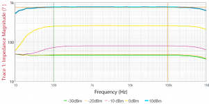
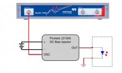
Some effect of the test jig? I have placed an inquiry. The baseline 50 ohm Caddock is ruler flat when using the J2130A DC Bias Injector.
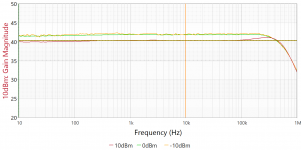
Using the "Gain" method, I get consistentcy -- Z at -10dBm, 0dBm and +10dBm:
Using the "Gain" method, I get consistentcy -- Z at -10dBm, 0dBm and +10dBm:
Attachments
To sum up your results?
How would these results show up in the operation of the 6j5 as a driver tube for a single ended amp? Your data seems to show that at certain times the LED would go into cut off and be very non linear .
Some effect of the test jig? I have placed an inquiry. The baseline 50 ohm Caddock is ruler flat when using the J2130A DC Bias Injector.
Using the "Gain" method, I get consistentcy -- Z at -10dBm, 0dBm and +10dBm:
How would these results show up in the operation of the 6j5 as a driver tube for a single ended amp? Your data seems to show that at certain times the LED would go into cut off and be very non linear .
How would these results show up in the operation of the 6j5 as a driver tube for a single ended amp?
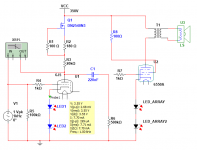
Just like an 6SN7.
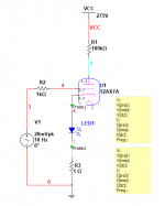
6J5 is half a 6SN7 with an attachment (pin1) to the can. This is cobbled together from one of SY's ideas -- use two LED's to bias the 6J5 to 8mA. The DN2540 is a $0.80 part and one is almost as good as two!
You can decide the circuitry around the 6550/807 etc/
Attachments
In other words the problem with the tube going into cut off as the current goes below a certain amperage is not an issue as you pointed out with the first graph?
Hi Ron, I did not ponder this statement, which is the case for the amp that i have. The actual bias resistor that i chose for the 6j5g is 400 ohm. I like the way the amp sounds but wanted to explore some different arrangements, and installing a led is very simple.
Is there a work around the increased gain or should i even worry about it? Thanks again
Note that if the 6J5 in your circuit uses its 1k resistor with no bypass capacitor, then it's using current feedback from the unbypassed cathode resistor. Putting an LED in there will ruin that. (Gain will go up quite a bit.)
I think the best discussion of using LEDs for cathode bias of tubes is found in Morgan Jones' "Valve Amplifiers" (3rd Edition, also in the 4th Ed.).
Hi Ron, I did not ponder this statement, which is the case for the amp that i have. The actual bias resistor that i chose for the 6j5g is 400 ohm. I like the way the amp sounds but wanted to explore some different arrangements, and installing a led is very simple.
Is there a work around the increased gain or should i even worry about it? Thanks again
In other words the problem with the tube going into cut off as the current goes below a certain amperage is not an issue as you pointed out with the first graph?
If the tube, or the LED, goes anywhere NEAR "cutoff", we are far-far past any hope of "clean amplification". So Not An Issue.
Hi Ron, I did not ponder this statement, which is the case for the amp that i have. The actual bias resistor that i chose for the 6j5g is 400 ohm. I like the way the amp sounds but wanted to explore some different arrangements, and installing a led is very simple.
Is there a work around the increased gain or should i even worry about it? Thanks again
The increased gain from using an LED for cathode bias is the same as if you put a 470uF capacitor in parallel with your 400 ohm cathode bias resistor.
Have you read up on how with a triode, a cathode load resistor that is not bypassed by a capacitor induces negative current feedback through the cathode?
Try reading this, especially the section "The common-cathode amplifier configuration - unbypassed cathode"
Designing Common-Cathode Triode Amplifiers
--
No, i understand that the unbypassed cathode resistor also has some negative current fb, but i was more concerned about the amount of increased gain the circuit will now have and if there would be negative aspect to the increased gain. Perhaps there will be more noise in the driver circuit? I guess in the end i will have to try and see which way i like more.The increased gain from using an LED for cathode bias is the same as if you put a 470uF capacitor in parallel with your 400 ohm cathode bias resistor.
Have you read up on how with a triode, a cathode load resistor that is not bypassed by a capacitor induces negative current feedback through the cathode?
Try reading this, especially the section "The common-cathode amplifier configuration - unbypassed cathode"
Designing Common-Cathode Triode Amplifiers
--
It seems that some have tried LED bias and at first blush it is an improvement but long term enjoyment is not as overall pleasing as just a good resistor? thank you for your input
The noise would be lower with an LED, no matter the stage gain , but the distortion generated by the valve in high gain (cap//resistor=led ) are higher than using a resistor , while if you're using global feedback with higher gain of the driver would give lower distortion figures and clipping can be avoided.
I'm looking at some data sheets and seeing wide Vf tolerances for some LEDs. The HLMP-60000 Red LED is listed as Vf=1.6v, min. 1.4v and max 2.1V, all at 10ma. And yet there are charts in Valve Amplifiers showing Vf against current to the hundredth of a volt!
What kind of consistency can one really expect? Here I am carefully designing for around 1.55v and the datasheet says it could be 2.1 v! A big difference on a 12ax7...
Also, I looked up the low current Kingbright Red LED cited earlier in the thread (p.6?) and found all kinds of warnings about how very fragile the thing is and to wear electrostatic gloves when handling it. Is this true of all LEDs? How robust are these things, really?
- Home
- Amplifiers
- Tubes / Valves
- LED tube biasing, pros and cons