It sounds as horrible as a piece of wire ?TL431 has a dynamic impedance of 0.2...0.5 ohms...
Then all fixed bias circuits should sound too, but why they do not ?
I guess the worry with TL431 type circuits is if they unknowingly move in to either non-linear extremity region for part of a waveform. Some may not realise how a supposed class A action of output stage devices can deviate, especially if the common cathode current includes grid and screen currents, mu imbalance, and non-ideal transformer windings.
a resistor paraleled by a capacitor is also providing a quasi-fixed bias at ac , that is why many people would prefer less gain and better distortion figures by giving up the capacitor.Better S/N ratio and higher gain is not allways what we need in a valve amp.Way too many possibilities outhere!
I was wondering if there is any reason to try LED biasing of a 6j5 in a SE amp where this tube is the driver for a 6550? I am using a 1w resistor now. If i put the LED in how do i set it up other than just replacing the resistor? I know different LED colors correspond to different voltage requirements. Does that mean i need to select the color according to my voltage drop? Thanks for all the help.
I don't see any recommended cathode resistor values under 1.3K. How do you control the tube current to a specific value to keep it under max dissipation if an LED has no set resistance? What supply voltage will the LED see on the cathode? You have to know that to restrict the current through any LED. Will you use an LED and a current limiter resistor? What's the point of the LED then?
Last edited:
I don't see any recommended cathode resistor values under 1.3K. How do you control the tube current to a specific value to keep it under max dissipation if an LED has no set resistance? What supply voltage will the LED see on the cathode? You have to know that to restrict the current through any LED. Will you use an LED and a current limiter resistor? What's the point of the LED then?
not sure what you are getting at. The led will have a fixed current use. The led determines the voltage thru the cathode. The resistor if you use both is to provide degenerative feedback. But i had not tried that yet.
not sure what you are getting at. The led will have a fixed current use.
Can you calculate what the current will be?
Yes.Can you calculate what the current will be?
If you want to use tube (for example D3a as triode), at the required operating point (for example 175V anode voltage, 10mA current) the grid voltage is -2V (from datasheet).
You can use R//C cathode complex (2V/10mA=200R paralleled with appropriate capacitor), or any device, which is produce 2V if 10mA current flowing through it.
The old type 5mm green LED is such a device....if the current swing not too much.
If you use CCS as anode load, the current is virtually invariable, so reverse voltage of LED is stable.
If your 6J5 has a 1k cathode bias resistor and is drawing 4mA plate current, then you need -4V grid bias, or +4V at the tube's cathode. To achieve that, use two green LEDs in series from the tube's cathode to ground to get +4V at the tube's cathode.
Note that if the 6J5 in your circuit uses its 1k resistor with no bypass capacitor, then it's using current feedback from the unbypassed cathode resistor. Putting an LED in there will ruin that. (Gain will go up quite a bit.)
In the first statement why not use a single blue led which will be close to the 4v drop?
In the second statement someone mentioned using a led followed by a resistor or is it a resistor followed by a led to have some feedback. Is that applicable here?
There are LEDs 2.8Vf 1.5mA?
Each LED's forward voltage is extremely insecure at such small current.
")
Led's are totally favoured in low noise preamps, but they are pretty useless in power amplifiers as you need to controll the distortion figures locally , more than you could do with a global feedback using the higher amplification given by the LED low dynamic resistance .The schamatic run in a symulator could tell us more about the LED +global NFB vs Resistor .+ local NFB
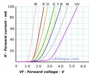
Regarding that graph showing LED Vf vs. If...
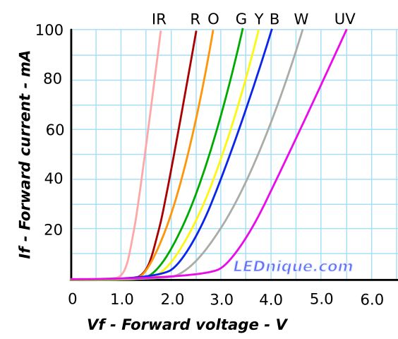
The Vf is related to the internal resistance of the LED at various points along the If/Vf curves. The internal resistance (let's call it Ri for now) stays pretty constantly low once there's more than 5mA of If. Below that, the LED's Ri goes up.
However in real life, using class A small-signal circuits, since the plate current of the tube stays constant, Vf of the LED stays fairly constant too. It's when you have wide fluctuations of current that the LED's Vf will vary widely in sympathy.
Taking a 12AX7, if the triode draws a constant 1mA plate current, that's what will be the LED's If as well. The Ri of the LED may be higher than it would be at If=5mA, but since the current going through it won't vary much at all, the Vf stays constant. So in the real world, tests have shown that using a cheap red LED to get about +1.6V at the cathode of a 12AX7 works fine.
See M. Blencouwe "Building High Fidelity Tube Preamps" pp. 244-46
--
Edit to add:
There are some low-current LEDs that are specified to attain their Vf at 1.5mA. I got a few to try with 12AX7 or 6SL7, but haven't used one yet.
Here's one rated for operation at If of 2mA:
https://www.vishay.com/docs/83343/tlle4401.pdf
Last edited:
With low anode signal voltages (as per input or close to input stages), the anode voltage will only swing say up to 10-20% of the stage supply voltage. How much the LED's incremental resistance varies through a cycle of the signal voltage will depend on the anode's idle bias voltage, and most change in LED incremental resistance would occur if the signal forced the anode in to the cut-off region. The anode resistive loadline still determines where the signal swings the anode voltage to, with the idle operating point being much more accurately identified on the anode curves by the intersection of a constant Vg curve with the loadline.
Last edited:
- Home
- Amplifiers
- Tubes / Valves
- LED tube biasing, pros and cons