I was wondering if there is any reason to try LED biasing of a 6j5 in a SE amp where this tube is the driver for a 6550? I am using a 1w resistor now. If i put the LED in how do i set it up other than just replacing the resistor? I know different LED colors correspond to different voltage requirements. Does that mean i need to select the color according to my voltage drop? Thanks for all the help.
I know this is covered in many previous threads and articles, as well as a few books. Quick answers:
Installing an LED for cathode bias is as simple as it gets. Just install from cathode of tube to ground, with the LED's cathode connecting to ground (LED anode to tube's cathode). The LED simply replaces the resistor and its bypass capacitor.
Different color LEDs exhibit different forward voltage drop. Rough estimates of color vs. V drop:
1N4148 diode = 0.7V (approx)
Infrared = 1.2V
Red = 1.8V to 2.0V
Green = 1.9V to 2.2V
Yellow = c. 2V
White = 3.2V (roughly)
Blue = 3.6V to maybe 4V
Note that there are kazillions of different LEDs made, each with slightly different forward voltage drop. They can vary quite a bit. You may need to buy a batch and test them for yourself.
The voltage across the LED goes up slightly with increasing current.
Most standard package LEDs have max current capacity of 20mA.
You can put LEDs in series to achieve higher voltage. They simply add.
If your 6J5 has a 1k cathode bias resistor and is drawing 4mA plate current, then you need -4V grid bias, or +4V at the tube's cathode. To achieve that, use two green LEDs in series from the tube's cathode to ground to get +4V at the tube's cathode.
The desirable quality of LED cathode bias is that you get the desired voltage drop with very little internal resistance. It's like a cathode resistor with a large value bypass capacitor in one easy to use part, which lights up to tell you it's working.
Some people say using an LED for cathode bias makes the tube 'sound more solid-state.' No comment from me on that.
Note that if the 6J5 in your circuit uses its 1k resistor with no bypass capacitor, then it's using current feedback from the unbypassed cathode resistor. Putting an LED in there will ruin that. (Gain will go up quite a bit.)
I think the best discussion of using LEDs for cathode bias of tubes is found in Morgan Jones' "Valve Amplifiers" (3rd Edition, also in the 4th Ed.).
everything put on the cathode have a big influence on the sound, unbypassed resistor , resistor/cap, led , schottky diodes, CCS , battery ,..
my own choice will be fixed bias at first but if i can't i will take unbypassed resistor ( with R under 200ohm)
than schottky diodes , resistor /cap led will be the last
my own choice will be fixed bias at first but if i can't i will take unbypassed resistor ( with R under 200ohm)
than schottky diodes , resistor /cap led will be the last
Just because an LED has a certain forward voltage doesn’t mean that it is low impedance - and a high Z LED militates against its use.
Example of a high Z LED?
According to Morgan Jones (in his book "Valve Amplifiers") a blue LED he measured gave Vdrop of 3.7V with internal resistance of 30 ohms. Is that considered 'high'?
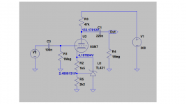
TL431 would be excellent replacement for a LED and adjustable between 2.5 V up to 37 V.
General features:
General features:
• Low Dynamic Output Impedance, 0.22 ? Typical
• Sink Current Capability of 1.0 mA to 100 mA
TL431 would be excellent replacement for a LED and adjustable between 2.5 V up to 37 V.
Good one! And its data sheet says it can sink up to 100mA. I wonder why we don't see this mentioned more often.
However, wouldn't TL431 have the same problem at low voltages that something like an LM317 (used as a ccs) would have? TL431 reference voltage is 2.5V, so at least that plus a little more must be dropped across the device for it to function. Let's say you use it in this hypothetical 6J5 drawing 4mA plate current, with +4V at the 6J5 cathode. Doesn't that mean the resulting 6J5 with Ip=4mA using TL431 for cathode bias can only accept 1.5V of input signal before the TL431 is in danger of dropout?
But for a driver stage with a 'tall' bias, like a 6J5 with more like Vk=6V and Ip=8mA, a TL431 looks like a great option. Thanks for the tip!
--
Last edited:
However, wouldn't TL431 have the same problem at low voltages that something like an LM317 (used as a ccs) would have?
No it does not, because it is not connected as a CCS. It is a CVS and keeps the grid to cathode voltage fixed as long as some (less than) 0.5 mA current flows thru it (and the tube).
Last edited:
LEDs
You make a fair point. I counter that tho' with this: it would take an exceptional LED to show a significant ΔV / ΔI (≡ “Z”) slope around its nominal VF forward recombination voltage.
One significant possibility is that an exceptional LED has an integral series "ballast" resistor inside its package. Or with more sophistication, an integral constant-current regulator (which isn't terribly hard to make: a lightly doped JFET is a compelling constant current regulator.)
But I've only seen one of these in my entire life so far. I've been “doing microelectronics” for 55 years now. From the dusk of vacuum tubes… LOL…
No. We just need to think of LEDs as diodes with a relatively high VF recombination voltage¹ and an also — entirely serendipitous — nearly temperature invariant VF as well. Before LEDs were available in the shorter wavelengths (i.e. blue-green, blue, deep blue, UV and 'white') … the VF ranged from 1.6 to 2.2 volts nominally. RED and YELLOW, and yellow-green.
While perhaps OK (onesies) for preamp or front-end input stage biasing, they didn't have the current carrying to make good biasing on downwind stages. At the core too was manufacturing variance. You could buy “a bag” of 100 to 1000 inexpensive LEDs, set up a test jig with a voltmeter and a whetstone bridge, and while watching the TV, test-and-bin all the LEDs in a few hours. Then become vexed to realize that the clustering of VF relative to IQ was so variable. Manufacturing variance.
Today however, because LEDs are being made with exactly the chip-making technologies used for our fantastically complex smartphone chips, the precision and repeatability of manufacturing big wafers of LEDs all-at-the-same-time has peaked.
I bought a “1,000 bag” of tiny bright blue LEDs for $3.50 on EBay; unlike the 1970s, I now have a 4½ digit multimeter and an older HP metrology 10 PPM reference variable voltage supply… so “testing and binning” the LEDs doesn't even require setting up a whetstone bridge for high accuracy.
Quite to my bemusement, there were only TWO LEDs that didn't “bin” to the same ±0.1% “bin” of VF as the others. Being only 2 of them, I just chucked 'em in the rubbish bin. T'heck with them.
Moreover, the "1,000 bag" was apparently weighed-to-count, and there 1,060 LEDs in the bag. (All were “double tested” for both VF and apparent brightness, non-quantitatively, at 1, 2, 5, 10, and 20 milliamps by rotary switch, and being inserted on a plugboard between two LEDs used as output-brightness references.) It took about 2 hours to test 'em all.
SEPARATELY I have advocated using simple 1N4148 or 1N4001 type ubiquitous budget rectifier diodes in series as simple-to-tune VF cathode bias solutions. No pretty green or blue glow, but solid-as-a-rock performers. Thing is, that when a few are tied end-to-end in a series chain to get say “4 volts”, within the ±30oC tube chassis operating temperature range (or more!) the VF for non-LED diodes varies by a few percent. Enough to mung the original biasing purpose? No… not really.
Before LED biasing became popular, I was using string-of–1N4001 diodes to create the raised cathode bias point all the time. All those 30+ year old amplifiers are still in use. It works. And frankly, in the days when “good” resistors were ±10% accurate devices, and we all used them without binning for cathode biasing … and with the ±25% variation of tube operating points, ±40% “life-curve” operating point drift of tubes in service, and the ±10% line voltage variation, having a 10% binned bunch of resistors was easy to work around.
A chain-of–1N4001's having ±3% VF thermal drift was the least of my problems.
So, just saying: it would be mighty rare to find a bunch of LEDs that exhibited “high Z” impedance, without being engineered to do so as a side-effect of some other purpose-and-function ideal.
GoatGuy
_______
¹ recombination potential — for the curious, all solid-state diodes work by having a "P" (shortage of electrons) and "N" (surplus of them) pair of layers molecularly bonded into a so-called PN junction. Wires are attached, and simplistically, there you are. A diode.
When current passes thru in the forward direction, electrons jump from the N side to the P side, and “recombine” with “holes” left in the crystal lattice valence electron cloud on the P side. Because quantum physics requires it, every last recombination is accompanied by a photon emission in “recombination”.
For 1N4001 thru 1N4007 silicon, the recombination energy is low enough that the photons aren't visible to the human eye. (But they are to infrared cameras!) For LEDs, the materials have higher “bandgap energy” differences between the P and N sides.
Binary and tertiary semiconductors such as gallium arsenide GaAs, indium telluride InTe, indium aluminum phosphide InAlP, also known as III-V binaries are used to get bandgap energies of 2 to 4 volts, generating in turn respectively, yellow-to-UV photons in our modern high efficiency LEDs. Since there is almost no color variation with temperature, it is a pretty good bet that the VF also doesn't vary much for LEDs, by temperature.
Just because an LED has a certain forward voltage doesn’t mean that it is low impedance - and a high Z LED militates against its use.
You make a fair point. I counter that tho' with this: it would take an exceptional LED to show a significant ΔV / ΔI (≡ “Z”) slope around its nominal VF forward recombination voltage.
One significant possibility is that an exceptional LED has an integral series "ballast" resistor inside its package. Or with more sophistication, an integral constant-current regulator (which isn't terribly hard to make: a lightly doped JFET is a compelling constant current regulator.)
But I've only seen one of these in my entire life so far. I've been “doing microelectronics” for 55 years now. From the dusk of vacuum tubes… LOL…
No. We just need to think of LEDs as diodes with a relatively high VF recombination voltage¹ and an also — entirely serendipitous — nearly temperature invariant VF as well. Before LEDs were available in the shorter wavelengths (i.e. blue-green, blue, deep blue, UV and 'white') … the VF ranged from 1.6 to 2.2 volts nominally. RED and YELLOW, and yellow-green.
While perhaps OK (onesies) for preamp or front-end input stage biasing, they didn't have the current carrying to make good biasing on downwind stages. At the core too was manufacturing variance. You could buy “a bag” of 100 to 1000 inexpensive LEDs, set up a test jig with a voltmeter and a whetstone bridge, and while watching the TV, test-and-bin all the LEDs in a few hours. Then become vexed to realize that the clustering of VF relative to IQ was so variable. Manufacturing variance.
Today however, because LEDs are being made with exactly the chip-making technologies used for our fantastically complex smartphone chips, the precision and repeatability of manufacturing big wafers of LEDs all-at-the-same-time has peaked.
I bought a “1,000 bag” of tiny bright blue LEDs for $3.50 on EBay; unlike the 1970s, I now have a 4½ digit multimeter and an older HP metrology 10 PPM reference variable voltage supply… so “testing and binning” the LEDs doesn't even require setting up a whetstone bridge for high accuracy.
Quite to my bemusement, there were only TWO LEDs that didn't “bin” to the same ±0.1% “bin” of VF as the others. Being only 2 of them, I just chucked 'em in the rubbish bin. T'heck with them.
Moreover, the "1,000 bag" was apparently weighed-to-count, and there 1,060 LEDs in the bag. (All were “double tested” for both VF and apparent brightness, non-quantitatively, at 1, 2, 5, 10, and 20 milliamps by rotary switch, and being inserted on a plugboard between two LEDs used as output-brightness references.) It took about 2 hours to test 'em all.
SEPARATELY I have advocated using simple 1N4148 or 1N4001 type ubiquitous budget rectifier diodes in series as simple-to-tune VF cathode bias solutions. No pretty green or blue glow, but solid-as-a-rock performers. Thing is, that when a few are tied end-to-end in a series chain to get say “4 volts”, within the ±30oC tube chassis operating temperature range (or more!) the VF for non-LED diodes varies by a few percent. Enough to mung the original biasing purpose? No… not really.
Before LED biasing became popular, I was using string-of–1N4001 diodes to create the raised cathode bias point all the time. All those 30+ year old amplifiers are still in use. It works. And frankly, in the days when “good” resistors were ±10% accurate devices, and we all used them without binning for cathode biasing … and with the ±25% variation of tube operating points, ±40% “life-curve” operating point drift of tubes in service, and the ±10% line voltage variation, having a 10% binned bunch of resistors was easy to work around.
A chain-of–1N4001's having ±3% VF thermal drift was the least of my problems.
So, just saying: it would be mighty rare to find a bunch of LEDs that exhibited “high Z” impedance, without being engineered to do so as a side-effect of some other purpose-and-function ideal.
GoatGuy
_______
¹ recombination potential — for the curious, all solid-state diodes work by having a "P" (shortage of electrons) and "N" (surplus of them) pair of layers molecularly bonded into a so-called PN junction. Wires are attached, and simplistically, there you are. A diode.
When current passes thru in the forward direction, electrons jump from the N side to the P side, and “recombine” with “holes” left in the crystal lattice valence electron cloud on the P side. Because quantum physics requires it, every last recombination is accompanied by a photon emission in “recombination”.
For 1N4001 thru 1N4007 silicon, the recombination energy is low enough that the photons aren't visible to the human eye. (But they are to infrared cameras!) For LEDs, the materials have higher “bandgap energy” differences between the P and N sides.
Binary and tertiary semiconductors such as gallium arsenide GaAs, indium telluride InTe, indium aluminum phosphide InAlP, also known as III-V binaries are used to get bandgap energies of 2 to 4 volts, generating in turn respectively, yellow-to-UV photons in our modern high efficiency LEDs. Since there is almost no color variation with temperature, it is a pretty good bet that the VF also doesn't vary much for LEDs, by temperature.
No it does not, because it is not connected as a CCS. It is a CVS and keeps the grid to cathode voltage fixed as long as some (less than) 0.5 mA current flows thru it (and the tube).
Thanks for the info! Yes, that is a very attractive part for this application. I could have used a couple of those for the headphone amp I just built, to get +2V at the cathode with plate current of 55mA. Better yet, I could have experimented with slightly different grid-cathode voltages instead of accepting the +2.2V I got from paralleled green LEDs. Next time...
Thanks for all the replies! I have read about LEDs here and there, but a more in depth discussion was just what i was interested in. I will give it a go when i get my son who is over 6 foot to move my 60lb amp to the shop . Cheers.
Attachments
Last edited:
Example of a high Z LED?
According to Morgan Jones (in his book "Valve Amplifiers") a blue LED he measured gave Vdrop of 3.7V with internal resistance of 30 ohms. Is that considered 'high'?
See the “Red Light District” thread. I think thats where I posted some measurements. I am about 3.5k-miles away from the data!
I have a large batch of surplus 5mm amber LEDs which I use for restorations where the original circuit does not 'need' to be followed. They measure 1.70 to 1.80V over a 0.1 to 1mA range, with an incremental resistance that varies from 500 to 60 ohm respectively. So equivalent to about 20uF bypass at 100Hz, but of course a LED is not frequency selective.
When using a central spigot noval or 7-pin valve holder, it is very convenient to solder directly from spigot to pin, and so avoid the 'space' and wiring for a bypass cap.
The cathode signal current will modulate the idle current, and hence the incremental resistance presented by the LED. Not an issue, and perhaps a blessing, for guitar amp use.
I have tried several times tl431 on cathode, it sounds horrible.
I have used it too and it performs extremely well.
Please, show your circuit for analysis.
This was mine, 6N6P PP (AB2):
Attachments
- Home
- Amplifiers
- Tubes / Valves
- LED tube biasing, pros and cons