When I look at the generic Futterman OTL architecture (picture #1) it seems obvious that the upper tube operates as a cathode follower while the lower tube is a grounded cathode. But that is not the case, they say. Both tubes are said to operate as grounded cathodes. Now, can anybody explain to me, how can a tube with plate connected to a power supply and cathode connected to the load - as the upper output in the original Futterman - ever be considered a grounded cathode.
In the inverted Futterman architecture however (picture #2), both tubes are said to operate as cathode followers. How can a tube with cathode connected to a power supply and plate connected to the load - as the lower output in the inverted Futterman - ever be considered a cathode follower.
What criteria make a tube behave as a CF or a GC when it is not the way they are connected to load and PS ?
Attachments
...not the case, they say.
What criteria make a tube behave as a CF or a GC when it is not the way they are connected to load and PS ?
Who "they"? Anonymous strawmen are hard to argue with.
"Ground" is arbitrary, and often confusing.
"Grounded cathode" is a nickname and can steer you wrong.
Look at the IN and OUT connections.
We have a 2-pin source, a 2-pin load, and a 3-pin device. However you connect them, one device pin must be "common" to both input and output.
Thus we get Common Kathode, Common Grid, Common Anode.
The three possibilities are shown below.
Attachments
Sorento, try to solve this by using a transformer as the driver for the tubes in series. For instance, by connecting the (isolated) secondaries (out of phase) to grid and cathode and then both triodes work as grounded cathode. Now try to figure out how the secondaries must be connected for both triodes to work as cathode follower...
1st problem:
The schematics in the two images are reversed. The formulas are in the right place though. [ I wonder how many OTLs have been built wrong! ]
Looking at the 1st (left) image, the top drive is developed across a load resistor with AC ground at top and V1a has its plate at AC ground. So cathode follower output. The bottom drive is also developed across a load resistor with the V2a plate as the driver load reference, so cathode follower drives.
Looking at the 2nd (right) image, the V1a drive is developed with respect to V1a cathode (bottom R connected to top cathode). And V2a drive is developed with respect to AC ground. V2a cathode is also at AC ground, so both are grounded cathode drive.
Last edited:
The driver/splitter stage in both figures is referenced to the output voltage through its cathode load resistor.
So some further modification of the output Z needs to be taken into account beside just the output stage only CF or GK formulas.
The left figure needs: AC Vin = V2 and V3 grid drives sum.
The right figure needs: AC Vin = Vout + V1 and V3 grid drive sum.
Which now makes the left figure look like grounded cathode mode.
And makes the right figure look like cathode follower mode.
So the driver stage CFB is the dominant factor. Driver PFB for the left figure (top loop), and driver NFB for the right figure (top loop). Opposite for bottom loops.
So looks like the original figures are correct then (for -overall- circuit function).
Last edited:
@PRR: e.g. here: 6C33C-B OTL Amplifier - Background and OTL Circuits quote: "Julius Futterman published the most famous solution to the problem of a balanced drive for the SEPP. He proposed that the cathode resistor of a split-load phase inverter be returned to ground through the load, rather than to ground, as was the normal practice. This arrangement results in equal but opposite drive signals being applied between the grid and plate of both sets of tubes. He went on to claim that when so driven, the output tubes are operating as cathode followers. Unfortunately, this is not correct, and Futterman's driver design did not achieve cathode follower operation. This is because the 100% positive feedback introduced by standing the phase splitter on the output voltage effectively canceled the 100% negative feedback from the load that produces the cathode follower effect in the first place." unquote
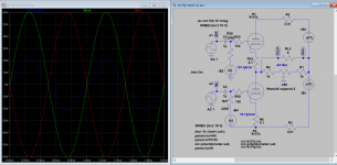
@smoking-amp: Thank you for your detailed reply, I've got to think it over for a while ... Still not quite there however; the question arose initially because I wanted to figure out what kind of drive the Tim Mellow's OTL is, and I am still lost ... CF or GC output ?
@smoking-amp: Thank you for your detailed reply, I've got to think it over for a while ... Still not quite there however; the question arose initially because I wanted to figure out what kind of drive the Tim Mellow's OTL is, and I am still lost ... CF or GC output ?
Attachments
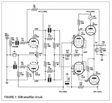
I wanted to figure out what kind of drive the Tim Mellow's OTL is, and I am still lost ... CF or GC output ?
If the bottom tube(s) has Nfb applied to it, then it's likely will "behave" like CF just like top tube. As there is Nfb applied to bottom tube via R13, the other arm of LTP has positive feedback so that that output of top is same as bottom, both "behave" like CF . There some more variations. The attached is also both CF (maybe GC, depend how you look at it?) but with equal driver level. You can search under "OTL Topologies" to know some others being discussed.
Attachments
Last edited:
...what kind of drive the Tim Mellow's OTL is... ?
Common Anode, both sides.
Attachments
Common Anode, both sides.
Thanks, got it now ...
When I look at the generic Futterman OTL architecture (picture #1) it seems obvious that the upper tube operates as a cathode follower while the lower tube is a grounded cathode.
Yes, they do. The topology is the same as that of a TTL gate. The big diference is that the output of a TTL is either high or low, and so you don't really care about any sort of balance. As an audio output stage, you don't want one half having higher gain than the other.
But that is not the case, they say. Both tubes are said to operate as grounded cathodes. Now, can anybody explain to me, how can a tube with plate connected to a power supply and cathode connected to the load - as the upper output in the original Futterman - ever be considered a grounded cathode.
Julius Futterman was an amatuer, not a professional. Look at that first schemo. V3 inverts the signal at its plate, and drives a cathode follower, so the voltage at RL is inverted. The signal at V3's cathode is in phase, and is inverted at V2's plate, so you have two additive voltages that are inverted with respect to the input to the cathodyne.
Futterman thought that returning the cathode resistor of V3 to the load would provide V2 with 100% NFB to make the common cathode half operate like a cathode follower. What he forgot to consider was that V3 doesn't "care" how its cathode is connected, its Vpk doesn't change. Since Vpk isn't changing, the feedback from the load "shoots through", appearing at V1's grid. That's 100% +FB that makes what was a cathode follower behave like a common cathode stage. It worked as this provides gain balance, but at the expense of higher Zo.
In the inverted Futterman architecture however (picture #2), both tubes are said to operate as cathode followers. How can a tube with cathode connected to a power supply and plate connected to the load - as the lower output in the inverted Futterman - ever be considered a cathode follower.
By cross connecting, the output voltage is in phase with the input. When the cathode resistor is connected to the hot side of the load, you still get that "shoot through", however this time, that feedback voltage is in opposition to the voltage at the grid, providing true NFB to the common cathode side, giving it the 100% NFB of a cathode follower. You have two cathode followers with their lower Zo
What criteria make a tube behave as a CF or a GC when it is not the way they are connected to load and PS ?
You have three internal elements: cathode, grid, and plate. You can use any one as the common element. The common cathode gives voltage and current gain. The signal is supplied between the cathode and grid, while the output is taken from the plate and cathode. High frequency performance is compromised by Miller Effect that increases the effective AC capacitance of Crt and therefore the input capacitance.
If the grid is the common element, the signal is applied between the cathode and grid while the output is between the plate and grid. This topology avoids Miller Effect, the unwanted feedback across Crt and better high frequency performance at the expense of Zi, and no current gain, though you do have voltage gain.
For a cathode follower, the plate is the common element, and the signal is applied between the grid and plate, with the signal take-off being between the cathode and plate. Again, you avoid Miller Effect, get better high frequency performance, current gain, but at the expense of voltage gain, which is always less than unity.
If you want to determine what topology you're dealing with, locate your common connection, and between which two elements the input is being applied.
Often ppl think that common anode is all there is to a cathodefollower, but depending on how you set the grid up there are profound differences on how the circuit performs
case 1
grid set to a positive voltage in respect to ground by any means other than with grid resistor taken from the junction of 2 resistors, one resistor to cathode the other to ground.
case 2
selfbiasing, grid dc level set with grid resistor taken from the junction of 2 resistors, one to cathode (often unbypassed), the other to ground.
How do you call case 2 to show the differences? High impedance CF? Inflated CF? Bootstrapped CF (I have difficulties to understand that name, not how bootstrapping functions, only the name)? Is there any special name for case 2?
Last edited:
Pulling yourself up by your bootstraps, i.e. enhancing your own performance without external means.(I have difficulties to understand that name, not how bootstrapping functions, only the name)?
An externally hosted image should be here but it was not working when we last tested it.
No, it's simply called self biased or cathode biased.Is there any special name for case 2?
I would say that there are subtle differences in how the circuit performs. Both DC coupled and self-bias are essentially cathode followers, given typical component values.gorgon53 said:Often ppl think that common anode is all there is to a cathodefollower, but depending on how you set the grid up there are profound differences on how the circuit performs
Pulling yourself up by your bootstraps, i.e. enhancing your own performance without external means.
No, it's simply called self biased or cathode biased.
Ahh, the equivalent to Muenchhausen pulling himself out of the swamp by pulling on his hair. Good description of what is going on
Thnx
Last edited:
I would say that there are subtle differences in how the circuit performs. Both DC coupled and self-bias are essentially cathode followers, given typical component values.
sure, both are CF, but in my view, there are more than just subtle differences. I once tried to be clever and reduced Rg of a selfbiased CF to a value still giving a high enough appearend lf-input impedance of approx. 1Mohm. I did this, because I very much disliked the use of multi-Mohm carbon resistors in a voltage divider with high voltage across. The outcome was not exactly what I hoped for, output impedance went up appriciable.
No free lunch
Last edited:
> Muenchhausen pulling himself out of the swamp by pulling on his hair
Exactly. (Though it seems easier to pull your belt than your pigtail or boots.)

Apparently 'bootstrap' comes from the US in the early 1800s (well after the original and the revised Munchausen tales were published).
Why The Phrase 'Pull Yourself Up By Your Bootstraps' Is Nonsense | HuffPost
The Big Apple: “Pull yourself up by your bootstraps”
Exactly. (Though it seems easier to pull your belt than your pigtail or boots.)
Apparently 'bootstrap' comes from the US in the early 1800s (well after the original and the revised Munchausen tales were published).
Why The Phrase 'Pull Yourself Up By Your Bootstraps' Is Nonsense | HuffPost
The Big Apple: “Pull yourself up by your bootstraps”
Yes, as I said "typical component values". If you use unusual values then you need to be aware of the detailed behaviour of the circuit.gorgon53 said:I once tried to be clever and reduced Rg of a selfbiased CF to a value still giving a high enough appearend lf-input impedance of approx. 1Mohm. I did this, because I very much disliked the use of multi-Mohm carbonresistors in a voltage divider with high voltage across. The outcome was not exactly what I hoped for, output impedance went up appriciable.
Using a CF to bootstrap an anode load can catch people out, because again the output impedance rises significantly - and for roughly the same reason as your circuit with small Rg. In both cases the previous stage gets extra loading which reduces its gain when the CF output is loaded - this is equivalent to raising the CF output impedance.
- Status
- This old topic is closed. If you want to reopen this topic, contact a moderator using the "Report Post" button.
- Home
- Amplifiers
- Tubes / Valves
- When is a Cathode Follower not a CF ?