The last months I have been building a diy tube preamp. It is not my first diy tube preamp, probably my 6th or 7th? All the others I have used point to point connection, and not pcb.
The Muffsy BSTRD - Class A Tube Preamp PCBs from muffsy on Tindie
I have build Remus(Swedish guy had an atricle in The Swedish Audio/Video around 1990?), ssss with ecc82, Forewatt srpp, and some other..
Have never had any problem with hum or noise, but today i fired up my "BASTARD" , yes its called that!, and it was like I was sitting near an old motorboat!, just noise...
What have I done wrong? I thought that to build with pcb-s was musch easier, nothing can go wrong? I think I have some skills, because I have been building tube preamps since the 1990s.
...and it was like I was sitting near an old motorboat!, just noise...
What is the "noise" in this case ?
High frequency hiss, 50 or 100 Hz based hum, slow frequency "motorboating" or what ?
Does the position of volume pot affect the noise level ?
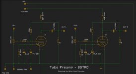
One heater pin (7) is directly connected to GND. Are you using DC-heater supply ? With AC the hum is very likely.
Last edited:
Here is a link to the schematic..
the bastard | theslowdiyer
Lot of stuff there, starting with a transistor scheme.
What would be better is a direct link to THE schematic, amplifier and power supply (since you say motoboating).
However this "seems" to be a stereo pair of 6J5 single-stage amplifiers. Such a thing can NOT oscillate (not even as a phase-shift oscillator), unless it is wired very wrong. So we need to see specifically what you have.
The Bstrd..line amp
Yes, it was like sitting in an old motorboat with a one cylinder motor...
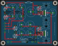
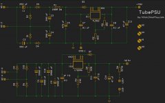
Here are schematics over the amp and psu. I have built the transformer into a seperate box.
Yes, it was like sitting in an old motorboat with a one cylinder motor...
Here are schematics over the amp and psu. I have built the transformer into a seperate box.
Attachments
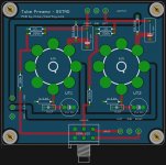
I placed the transistors on the bottomplate and isolate them from det aluminium. I used a piece of metal over the transistors, to mount them to the bottom plate, and connect the wires to the pcb. It looks like the pins of one of the transistors got "earthed" to the bottom plate because I pulled the wires when I soldered them to the pcb. I will test the pre again when I am back home.
The schematic shows at least one error, which can cause the heater supply regulator (IC: LT1086) to be unstable.
The offending part is C12 0.1µF - which would be no trouble for a LM317, but a LT1086 is a PNP output regulator which requires ESR in the output capacitor to compensate it.
The data sheet tells you to attach 22µF tantalum or 150µF Alu electrolytic. These have ESR values of 0.4 to 2Ω, which give a frequency-compensating zero (somewhere around 200-700kHz) in the loop gain, keeping the phase rotation under control.
Adding 0.1µF (ceramic or film caps) will have almost no ESR - bypassing the intended zero!
Please take that 0.1µF C12 out. Even if (by luck) it doesn't oscillate, the phase margin is badly degraded, an oscillation may set in at different temperatures, or with heaters of different tube brands.
The HV regulator should be checked for similar problems - which are quite likely, I suspect.
- Status
- This old topic is closed. If you want to reopen this topic, contact a moderator using the "Report Post" button.
- Home
- Amplifiers
- Tubes / Valves
- Noise in my DIY tube preamp