How about this:
Electra-Print.com 300B DRD Audio Tube Amplifier
Might be the same as the Welborne Labs version, might not.
Welborne Labs did use some of Electra Prints transformers, etc.
Electra-Print.com 300B DRD Audio Tube Amplifier
Might be the same as the Welborne Labs version, might not.
Welborne Labs did use some of Electra Prints transformers, etc.
Last edited:

Thank you so much RFBurns, this is exactly what I was after.
By any chance would you happen to know what alternative transformers would be suitable for the Welborne version?
Any chance that this can be shared?I have his book with schematics
Thanks 6A3sUMMER, I did come across this one, but I think the Welborne version operates at a lower voltage.How about this:
Electra-Print.com 300B DRD Audio Tube Amplifier
Might be the same as the Welborne Labs version, might not.
Welborne Labs did use some of Electra Prints transformers, etc.
6L6, thanks for the offer to help, I may have a few questions down the line, just trying to get all my ducks in a row at this point.I might have one but it would be buried deep away somewhere...
Are you looking for a specific piece of information? I build a few of them back in the day.
By any chance would you happen to know what alternative transformers would be suitable for the Welborne version?
Jay L and deafbykhorns,
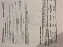
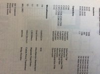
The Welborne DRD amplifiers were DC coupled from driver tube plate to output tube grid. The DRD are 2 tube amplifiers. The B+ is medium to high, because the DRD design has lots of drop in the output tubes self bias resistor. That voltage across the self bias resistor is connected to the driver tube's plate choke. The output tube's self bias resistor's voltage drop has to be large enough to run the B+ required by the driver tube plate. The driver choke has a fairly low DCR, so the B+ drop is less than if a plate load resistor was used. There were 3 Welborne DRD amplifiers, a 45, a 2A3, and a 300B version.
The 2 stage Loftin White 2A3 amplifier (also DC coupled) has to have medium to large B+ because the output tube self bias has to run the driver tube. But the voltage needs to be even larger, because the driver tube plate load resistor has a larger drop than the plate load choke DCR of the DRD amps.
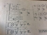
The power supply schematic in post #9 on the right is for the Welborne model Laurel amplifier, a 3 tube 300B amplifier. It is not a DRD amplifier power supply (look on the far lower right, you will see 'Laurel').
I met Ron Welborne at the early VSAC conferences in Silverdale Washington. I also met Jack Eliano of Electra-Print Audio (and have done business with him a number of times). They collaborated on the DRD amplifiers, but I do not know how many original and how many spinoff designs there may be.
I enjoyed the last VSAC Vacuum Tube State of the Art Conference in 2008 in Vancouver, WA. I presented a two part seminar, theory, and practical listening session then. VSAC 2008 ended a very nice conference series (sad to say).
I have a pair of the Electra-Print 3k to 2, 4, 8, 16 transformers, but I do not know if they were the exact ones used in the 300B DRD amp (they were made for 60 to 65 mA quiescent current).
The Welborne DRD amplifiers were DC coupled from driver tube plate to output tube grid. The DRD are 2 tube amplifiers. The B+ is medium to high, because the DRD design has lots of drop in the output tubes self bias resistor. That voltage across the self bias resistor is connected to the driver tube's plate choke. The output tube's self bias resistor's voltage drop has to be large enough to run the B+ required by the driver tube plate. The driver choke has a fairly low DCR, so the B+ drop is less than if a plate load resistor was used. There were 3 Welborne DRD amplifiers, a 45, a 2A3, and a 300B version.
The 2 stage Loftin White 2A3 amplifier (also DC coupled) has to have medium to large B+ because the output tube self bias has to run the driver tube. But the voltage needs to be even larger, because the driver tube plate load resistor has a larger drop than the plate load choke DCR of the DRD amps.
The power supply schematic in post #9 on the right is for the Welborne model Laurel amplifier, a 3 tube 300B amplifier. It is not a DRD amplifier power supply (look on the far lower right, you will see 'Laurel').
I met Ron Welborne at the early VSAC conferences in Silverdale Washington. I also met Jack Eliano of Electra-Print Audio (and have done business with him a number of times). They collaborated on the DRD amplifiers, but I do not know how many original and how many spinoff designs there may be.
I enjoyed the last VSAC Vacuum Tube State of the Art Conference in 2008 in Vancouver, WA. I presented a two part seminar, theory, and practical listening session then. VSAC 2008 ended a very nice conference series (sad to say).
I have a pair of the Electra-Print 3k to 2, 4, 8, 16 transformers, but I do not know if they were the exact ones used in the 300B DRD amp (they were made for 60 to 65 mA quiescent current).
Last edited:
Yes, but same power supply with increased secondary
More than likely a 450-0-450 transformer to get the voltage for DRD
One way to figure this out is witha variac and a spare transformer capable of outputting higher voltage but watch those cap voltages!
Jacks DRD design was driven hard from what i remember, he prefered it that way and used a 3k 100ma transformer
Last edited:
deafbykhorns,
1. Right, the Electra Print link I put on post #2 with the DRD schematic says: 90mA.
2. Be careful when using the Laurel power supply schematic. The electrolytic and the plastic caps that immediately follow the choke are only rated for 450V.
Using a transformer that has a 450 0 450V secondary will apply 636 Volts peak to the rectifier tube. Assuming a 50 Volt drop in the rectifier, that will be about 586 volts on those 450V capacitors. And all the other capacitors are only rated at 630V. If the rectifier warms up earlier than the other tubes, or if an output tube dies, all the 630V caps are going to be taken out too.
Hi, anyone know any reason why Welborne DRD should not have the 300b heater supply removed and a tentlabs regulated 5v AC module fitted in it place?
If you break one of these, the number of people who are out there who could sort one out is very small.
The last pair I had in my workshop were plenty quiet on the speakers posts. I don't recommend addressing problems that aren't there.
Apart from the reason mentioned by audiowize and added cost. No. If you are confident you can do it and can't leave well enough alone. Why not?Hi, anyone know any reason why Welborne DRD should not have the 300b heater supply removed and a tentlabs regulated 5v AC module fitted in it place?
Hi, anyone know any reason why Welborne DRD should not have the 300b heater supply removed and a tentlabs regulated 5v AC module fitted in it place?
Emission labs have some warranty restrictions with electronic filament supplies. If you plan on buying Emission labs 300B tubes, you should check if they accept Tentlabs.
Thanks for what is undoubtedly very good advice. Common sense tells me you're right, I've broken various stuff in the past fixing what ain't broke, but curiosity nudges me to have a go. Probably wiser to leave the Welbornes be and try them out on a home brew. It's just I've got a pair of the modules calling to me from the box of bits.
Anybody have the Welborne Labs 300B DRD (Tube Rectified) manual?
I did try using Wayback Machine to try and retrieve it, as it had been available there for free download, but it was not archived.
I have the manual - PM me for a copy.
I have the manual - PM me for a copy.
Thank you, it's much appreciated.
- Status
- This old topic is closed. If you want to reopen this topic, contact a moderator using the "Report Post" button.
- Home
- Amplifiers
- Tubes / Valves
- Welborne Labs 300B DRD (Tube Rectified) Manual