Nothing special about that one.
Looks like another poorly designed preamp.
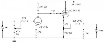
What's with the 470 ohm resistor in series with the 22k resistor on the cathode of the output section. Is this some kind of attenuator? Why?
You can probably lose both 220 ohm grid resistors as well.
Looks like another poorly designed preamp.
What's with the 470 ohm resistor in series with the 22k resistor on the cathode of the output section. Is this some kind of attenuator? Why?
You can probably lose both 220 ohm grid resistors as well.
Just for my curiosity, I simulated the grounded cathode with Tube Cad. I got about 6.2 Ma Bias current and 111 Volts across the tube. This represents about 25% of the allowed plate dissipation of the 12au7. These numbers are far too conservative IMHO, especially for an ecc82, which doesn't have a great reputation for linearity.I wander if it is any good?
About 19 dB, or about 9.3 X.And if it is, how much gain may I expect from it?
What's with the 470 ohm resistor in series with the 22k resistor on the cathode of the output section. Is this some kind of attenuator? Why?
Here is an explanation of the technique in the Glassware audio design software website.Link . As with all circuit techniques, your milage may vary.
")
If I were going to build a line amp in this style, I would use 6SN7 or 7N7 tubes, biased for at least 12 ma, and 200 + volts across the tube. Nothing really wrong with this design. Perhaps other designs might be better.
Cheers;
Doug
Topologically similar to the Foreplay.
Isn't that to get the voltages right for the direct coupling?
dave
Frank Berry said:What's with the 470 ohm resistor in series with the 22k resistor on the cathode of the output section. Is this some kind of attenuator? Why?
Isn't that to get the voltages right for the direct coupling?
dave
Hi,
Actually, it isn't.
At that point the DC coupling is done already as bias is set by the voltage difference between the voltage present at the anode of the first half of the twin triode and the bias set by the sum of both cathode resistors of the second half.
The difference between the two voltages than determines the gridbias of the second triode.
So the 470R is part of the mirror circuit, anode-cathode follower, allowing for some modicum of distortion cancellation.
Provided the two triodes are closely matched this should work.
No doubt you noticed that the anode resistor appears in the cathode of the CF and the cathode resistor of the anode follower is added on top and the output is taken from the joint between them.
I don't have a copy of the diagram but that's how I understand it's designed too.
Cheers,
Isn't that to get the voltages right for the direct coupling?
Actually, it isn't.
At that point the DC coupling is done already as bias is set by the voltage difference between the voltage present at the anode of the first half of the twin triode and the bias set by the sum of both cathode resistors of the second half.
The difference between the two voltages than determines the gridbias of the second triode.
So the 470R is part of the mirror circuit, anode-cathode follower, allowing for some modicum of distortion cancellation.
Provided the two triodes are closely matched this should work.
No doubt you noticed that the anode resistor appears in the cathode of the CF and the cathode resistor of the anode follower is added on top and the output is taken from the joint between them.
Topologically similar to the Foreplay.
I don't have a copy of the diagram but that's how I understand it's designed too.
Cheers,
IMO, the design is FINE. The 'U7 and the 'SN7 (plus its electrical relatives) are close enough in behavior to use the all values unchanged. How about an 8CG7 or 14AF7 with DC energizing the heater?
This "pup" or a variation just might meet my needs for a SLIGHTLY euphonic, LOW gain, line stage. Make the O/P coupling cap. 12 muF. Insert a Sowter model 8940 parafeed O/P trafo. Wire the trafo secondary to make the unit non-inverting as a whole. Float the trafo secondary to break up ground loops. Per Brian Sowter, a 10 KOhm resistor gets wired across the O/P RCA jack. Noise control is taken care of by wiring a 10 nF. ceramic cap. from the O/P RCA jack's grounding tab to the chassis. The icing on the cake would be CCS loading the cathode follower with a pentode.
This "pup" or a variation just might meet my needs for a SLIGHTLY euphonic, LOW gain, line stage. Make the O/P coupling cap. 12 muF. Insert a Sowter model 8940 parafeed O/P trafo. Wire the trafo secondary to make the unit non-inverting as a whole. Float the trafo secondary to break up ground loops. Per Brian Sowter, a 10 KOhm resistor gets wired across the O/P RCA jack. Noise control is taken care of by wiring a 10 nF. ceramic cap. from the O/P RCA jack's grounding tab to the chassis. The icing on the cake would be CCS loading the cathode follower with a pentode.
Hi,
Do you still need a CF if you're going to use a xformer anyway?
As for the rest of it, I'd personally give the SN7 and family a B+ of 300V or higher and run them at around 15mA...YMMV.
Cheers,
Make the O/P coupling cap. 12 muF. Insert a Sowter model 8940 parafeed O/P trafo. Wire the trafo secondary to make the unit non-inverting as a whole. Float the trafo secondary to break up ground loops. Per Brian Sowter, a 10 KOhm resistor gets wired across the O/P RCA jack. Noise control is taken care of by wiring a 10 nF. ceramic cap. from the O/P RCA jack's grounding tab to the chassis. The icing on the cake would be CCS loading the cathode follower with a pentode.
Do you still need a CF if you're going to use a xformer anyway?
As for the rest of it, I'd personally give the SN7 and family a B+ of 300V or higher and run them at around 15mA...YMMV.
Cheers,
>>Do you still need a CF if you're going to use a xformer anyway?<<
Yes, the CF is needed. The Sowter model 8940 is specifically designed to be used with AC coupled cathode followers. In addition, a CCS loaded CF buffering a resistively loaded common cathode triode fits in neatly with the SLIGHTLY euphonic, but essentially linear, voicing I want. This line stage will be used with a H/K Cit. 2 and an AVA FET-Valve. Both power amps are pretty "neutral" and a SMALL dose of euphony wouldn't hurt.
How does a 'CG7 run at a "textbook" 250 V. on the plate, -8 V. on the grid, and Ib = 9 mA "grab" you? Bias would be by a stack of 4X red LEDs and a 15 KOhm load resistor would be used. I figure the B+ rail has to be 393 V.
Eli Duttman said:The icing on the cake would be CCS loading the cathode follower with a pentode.
If one were to go to the trouble of adding another valve, especially
a pentode, I'd suggest using this as an anode load above the first
valve and of course removing the cathode follower.
This of course gives a Kimmel mu stage.
Then throw away the poor sounding 12AU7 and use say an E80CC instead
and you'll have a really fine sounding preamp.
It's called Nina, and the circuit and details are are on this board!
An Alan Kimmel mu stage is TOO linear for my purposes, I want a SMALL amount of 2nd harmonic distortion.
I suggested a 'CG7 as the tube, not a 'U7.
CCS loaded cathode followers sound BETTER than resistively loaded CFs do. Pentodes make good current sinks, as do N-channel FETs and NPN BJTs. Why use "sand", when a tube will do?
I suggested a 'CG7 as the tube, not a 'U7.
CCS loaded cathode followers sound BETTER than resistively loaded CFs do. Pentodes make good current sinks, as do N-channel FETs and NPN BJTs. Why use "sand", when a tube will do?
Eli Duttman said:An Alan Kimmel mu stage is TOO linear for my purposes, I want a SMALL amount of 2nd harmonic distortion.
OK, I understand, so a normal triode with anode load resistor it is then.
I suggested a 'CG7 as the tube, not a 'U7.
Oops, sorry, I was looking at the original cct.
CCS loaded cathode followers sound BETTER than resistively loaded CFs do. Pentodes make good current sinks
Fine, I accept this totally.
One thing to consider; how about just using a pentode as a cathode
follower? As I see it, the very high voltage gain gives good linearity,
and the generally highish Gm (relative to similar size triodes) will
give a low Zout, I think.
I wonder if, compared to triode CF with pentode sink, less might be more
if you see what I mean. I have no idea if that's right, just idly
speculating ...
"One thing to consider; how about just using a pentode as a cathode
follower? "
So here is your perfect exceuse to stock up on the 12BY7. Use 'em in the Cit.II or your linestage output. reisitive load will do the trick nicely, and at ~100 ohms output z, should drive your opt just fine.
regards,
Douglas
follower? "
So here is your perfect exceuse to stock up on the 12BY7. Use 'em in the Cit.II or your linestage output. reisitive load will do the trick nicely, and at ~100 ohms output z, should drive your opt just fine.
regards,
Douglas
Hi,
Don't you mean CCS sunk CFs here?
I just want to avoid confusion before anyone asks where to put the CCS here.
Cheers,
CCS loaded cathode followers sound BETTER than resistively loaded CFs do.
Don't you mean CCS sunk CFs here?
I just want to avoid confusion before anyone asks where to put the CCS here.
Cheers,
THE CONVENIENCE OF THE "S"...
Hi,
Eli,
What I meant is the use of the verb "to load" in conjunction with the CF's CCS.
With the anode follower the CCS (Constant Current Source either way to make my life easier) is used as a replacement load for the commonly used anode (plate to you) resistor.
Whereas in terms of a cathode follower the CCS is used to sink current away from the cathode so it replaces the commonly used cathode resistor that's usually tied to ground.
It's a matter of semantics, I know.
Cheers,
It's a "source" if connecting its far end to 0V causes a regulated current to flow, and a "sink" if when connected to 0V, no current flows, but when conected to an appropriate (non-zero) potential, a regulated current flows. How about that? There's a really easy-to-follow, succinct description! No wonder there's confusion.
Pentodes cathode followers don't work quite as well as their high mu promises. Even after the voltage between g2 and cathode has been arranged to be (nearly) constant. A bit of a disappointment, really.
Pentodes cathode followers don't work quite as well as their high mu promises. Even after the voltage between g2 and cathode has been arranged to be (nearly) constant. A bit of a disappointment, really.
- Status
- This old topic is closed. If you want to reopen this topic, contact a moderator using the "Report Post" button.
- Home
- Amplifiers
- Tubes / Valves
- Yet another valve pre, comments?!