I am curious about PP flea amps with things like 12AU7s for the output stage. It seems a popular thing for guitar but I don't see much for hi-fi. has anyone built or played with such things?
as you know guitar amp is not like hifi amp .no deep low frequency. and some times receive to maximum output... means distortion .so this benefit is good for guitar amp ...distortion by output
")
Attachments
Last edited:
I prefer the 5965 because they are $3 each.
Shh, don't let the cat out of the bag!
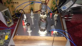
here's one
12ax7 12au7 pp
on page 40 of 76
https://www.americanradiohistory.com/Archive-Radio-Constructor/60s/RC-1964-10.pdf
12ax7 12au7 pp
on page 40 of 76
https://www.americanradiohistory.com/Archive-Radio-Constructor/60s/RC-1964-10.pdf

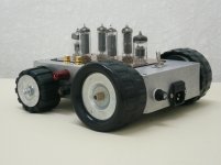
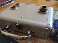
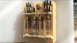
A PP flea power amp in a make-up case. Balanced inputs, no output transformer and yet more then 1 Watt output on 4 Ohm speakers. Needs only 12v PSU.
Used the David Berning “Micro Zotl" schematic as a starting point.
Used the David Berning “Micro Zotl" schematic as a starting point.
Attachments
One can get a very high primary impedance by using two small OTs in the Norman Crowhurst Twin Coupled configuration. (resulting in 2X that of each OT Zpri)
So an Edcor GXPP10-16-12K would give 24K P-P to 8 Ohm sec. (40 to 18KHz, 10 Watts) or
(20 to 18KHz at 2.5 Watts)
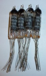
If you use some sub-mini tubes with good current capability, like 5902 (50 mA DC) or 5639 (40 mA DC), you could just use an off the shelf conventional 8K, 10K or 12K OT. (then there is 12HL7, 55 mA DC and 21000 gm for a no preamp stage P-P)
---------------------------------------------
RE: Lampie519
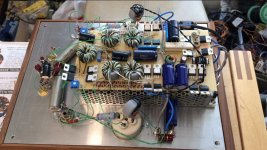
I'm impressed that someone would go to such lengths for such a small amplifier. It would seem easier to use an IC for the carrier frequency generation.
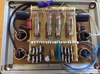
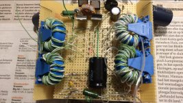
Looks like you have gone to extensive use of multifilar toroid xfmrs to minimize the leakage L (which is suffered at the carrier freq.). So I assume it operates satisfactorily without N Fdbk to keep the output impedance down. Someone should offer a small PC board for building such "OT"s conveniently.
So an Edcor GXPP10-16-12K would give 24K P-P to 8 Ohm sec. (40 to 18KHz, 10 Watts) or
(20 to 18KHz at 2.5 Watts)
If you use some sub-mini tubes with good current capability, like 5902 (50 mA DC) or 5639 (40 mA DC), you could just use an off the shelf conventional 8K, 10K or 12K OT. (then there is 12HL7, 55 mA DC and 21000 gm for a no preamp stage P-P)
---------------------------------------------
RE: Lampie519
I'm impressed that someone would go to such lengths for such a small amplifier. It would seem easier to use an IC for the carrier frequency generation.
Looks like you have gone to extensive use of multifilar toroid xfmrs to minimize the leakage L (which is suffered at the carrier freq.). So I assume it operates satisfactorily without N Fdbk to keep the output impedance down. Someone should offer a small PC board for building such "OT"s conveniently.
Attachments
Last edited:
Yes, that was his 2nd article on the "Twin Coupled" scheme. The general scheme is of using 2 OTs for making a 50% CFB OT. I don't see any mention there of figuring the secondary impedances, but two 16 Ohm secondaries in parallel drive an 8 Ohm load (each sees a 16 Ohm load). Or two 4 Ohm secondaries in series will drive an 8 Ohm load. The parallel 16 Ohms secondaries is safest for CFB accuracy.
Bootstrapping of the driver loads can be used if one doesn't want all of the 50% CFB. A pentode driver stage with load bootstraps essentially removes the full 50% CFB factor. An example shown.
A triode driver stage with bootstrapped loads will leave some of the CFB in place due to their Rp factors. McIntosh used this.
Last edited:
It was a nice little project. I had no issues building it. Resonates at ca. 500Khz and for the heaters i used a small ferrite toroidal as these tubes need 2.4 volt (center tab, directly heated cathodes). as for creating a board for the transformers is difficult as every one has different needs for output power and these toroids saturate easily.
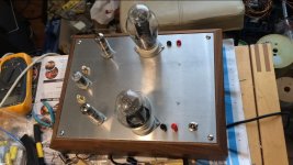
I have build also a single ended version (more power) but equally complex.
I have build also a single ended version (more power) but equally complex.
Attachments
Last edited:
Oh, so a resonant design way up at 500 KHz. This puts extreme stress on leakage L effects in the ferrite xfmrs. Have you measured the output impedance of the OTs to see if they conform to the expected xfmr turns ratio output impedance? N Fdbk around an LP filter seems to be necessary for the commercial versions.
For a DIY PC board, I would rather use a lowest acceptable freq. square wave carrier generated with controlled dead time slots and controlled slew rate (reduced BW) edges, by a PWM type chip. All the Mosfets, diodes and high side Mosfet drivers etc could be pre-configured on the PC board. Just add the DIY ferrites to terminals to complete. Some instructions on proper low leakage L winding of the ferrites included with it. Provision could be in place for optionally using two such boards in parallel, with 90 degree phase shifted carriers for continuous audio BW conduction.
With two 90 deg. overlapped conduction boards, they could even be designed with slightly different turns ratios. This would allow a variable transformation ratio OT (pot. knob adjust), by varying the PWM angle of each board in a complementary fashion.
Last edited:
- Status
- This old topic is closed. If you want to reopen this topic, contact a moderator using the "Report Post" button.
- Home
- Amplifiers
- Tubes / Valves
- Can we discuss PP Flea amps for hi-fi