I just built a flea power amp, SET though, not PP. It's based on a little Magnavox 83xx chassis which was a SE 6BQ5 amp that was used in portable record players and some of their cheaper consoles. It uses 12BH7 outputs with the plates in parallel. Kind of like a mini 2A3 except that it's not directly heated. Uses all the stock transformers, stock rectifier and input tube which simplifies things.
Since there seems to be some interest in flea power on here lately - I've also noticed the thread about a PP 6SN7 amp - I'll put some details up in a new thread.
Since there seems to be some interest in flea power on here lately - I've also noticed the thread about a PP 6SN7 amp - I'll put some details up in a new thread.
If you change the ratio of the transformers you also change the voltage suplied to the tubes. Then there will be a unbalance between them. This will add distortion. Don’t forget that the transformers are no ordenary output transformers. No dc flow as usual but only the signal difference between the transformers therefore balancing is crucial.
I was not suggesting changing the ratio between the P-P tubes, but rather the ratio of each 90 deg. phase of an overlapped complementary conduction single OT. (which uses two ferrite xfmrs for each tube). So the complementary PWM varies the amount of time in each cycle used by each ratio ferrite xfmr.
For P-P then one would similarly change the ratio for -both- OTs for both tubes. And so changing the transform ratio for the complete P-P output. This would only be practical obviously for an easy to build PC board based switching OT, since it requires twice as many components as usual.
Yes, true about the DC equivalent tube voltage varying with the Berning style switching OT design versus turns ratio. This -can- be useful, since a lower turns ratio typically calls for a lower B+ with more current. However, (see below), an alternate version of a switching OT exists which allows separation of B+ and turns ratio if desired.
--------------------------------------------------
The Berning style design does not allow separation of DC and AC components on the tubes, and is not suitable for a CFB design either (DC appearing in the cathode to grid space that is sensitive to speaker loading current, so not readily compensated). However, there has existed for some time an alternate configuration (discussed here years ago) that does. Instead of a switched OT per tube, it uses two dissimilar type ferrite xfmrs. One CT'd xfmr that powers both tubes at the same time alternatively (per carrier phase polarity). The other generates the B+ at the CT separately (ferrite switched also) Common rectifiers for each tube.
It IS possible to do CFB designs with this version, or variable turns ratio designs (without affecting B+). This allows variation of the transform ratio without altering the max DC on the tubes. Although applying complementary PWM to the B+ generating xfmr would allow separate variation of B+, parts count would go up even further.
The general design is still important though, since it allows CFB tube operation with no more parts than the Berning design. (ie, it is more flexible) Another thread would be needed to discuss the details further.
Last edited:
As you can see I am not scared of many components.. therefore I would like to try new design ideas especially if it leads to better amps. Smaller and more efficient. Until now I have not seen anything better then the Berning style amps therefore I was exploring the different options (single ended DHT and PP etc.) In the past I have build many chunky and extremely heavy OTL amplifier with great success but they can not be compared to these little amps as they just beat them , period.
If you have some link to a patent or schematic just to get an idea what you had in mind I will check it out !
If you have some link to a patent or schematic just to get an idea what you had in mind I will check it out !
Some links:
This thread discussed a huge range of novel ideas, including switched mode OTs.
Some of it is probably wrong or poorly thought out. I can't even follow some of it now. But the alternative versions of the Berning OT get discussed, the Matrix version is the last one I remember:
I still haven't found the schematic yet that I was looking for. A long thread. 10 years ago. When I find it... The basic idea was to use two center tapped ferrite xfmrs (like conventional P-P except with the HF commutating diodes at the plates) to operate both the P-P tubes (each xfmr complementarily active for opposite HF phase) and de-mod the differential HF audio modulated signal via the switching Mosfets from + and - LV supplies, similar to the Berning version.
http://www.diyaudio.com/forums/tubes-valves/118725-hybrid-12.html#post1464919
Switched capacitor OTs:
Switched Capacitor Impedance Converter
David Berning's zh-230 - whats going on here?
Last edited:
Wow! Thanks for sharing! A lot to read. I just hovered over the 3 topics and found the switched cap converter actually 100% equal to the Berning solution with 1 major drawback : bandwidth will be very limited as the caps will load the tubes unless the tube is a very high current version but then we can just built a regular OTL. But i will study more on this before i judge. Thanks again!
The switched capacitor OT can actually have less capacitance across the tube than a conventional OT. HF means very small caps, and high bandwidth charge transfer rate. The cap values can also be tapered in C value toward the tube.
There is even some kind of HF ceramic piezoelectric voltage converter that gets mentioned in there somewhere. Used for HV vacuum florescent displays I think.
The real point is that many schemes for voltage conversion can be used to make an OT. Linearity doesn't even matter much with the audio modulated on the HF carrier, since energy has to be conserved as long as the losses are some constant %.
And then there are parametric converters, where C or L is modulated by a power HF carrier. Parametric traveling wave transmission lines too, ferrite 2 or 4 hole beads strung on multi-mode transmission lines. A wire with power gain. That thread hasn't been written yet.
Last edited:
The 6BM8 is a triode and pentode in one 9 pin envelope. Not "flea power", but lets you build a stereo PP amp with just 2 tubes.
Would take 4. Nice SE spud though.
When I was researching the little 12BH7 SET that I just posted about here:
http://www.diyaudio.com/forums/tubes-valves/325366-flea-power-set-magnavox-12bh7-mod.html
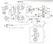
I came across a PP design by the famous Japanese designer Shishido and an old thread over on AA by a highly respected builder, Gary Kaufman, about his build of this amp. Audio Asylum Thread Printer
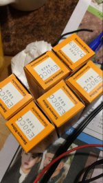
I wonder if the OT he used - a Fisher 500C with a 7.5k primary - is anywhere near the optimum value. It's certainly a massive OT considering the power output of the amp, which he estimates as 5 wpc. The Shishido design used a Tango U-15-8 which nobody seems to know anything about but I wonder if the "15" refers to a 15k primary and perhaps the "8" is the wattage rating??
The little Magnavox OT used in my SET has a primary impedance of 11.4k when used with 8 ohm speakers and I was told that 10.75k was optimum. So wouldn't 21.5k be optimum for a PP design using the 12BH7? Kaufman didn't say anything about the matter and doesn't mention if he was running 8 ohm speakers on the 4 ohm tap or 16 ohm speakers on the 8 ohm tap.
I have a nice pair of Chicago 10k PP OTs that might be useful for such a design but not sure if I'll try to build it or not. Too many other projects.
Anyway, since this is about PP flea power, maybe someone here will be interested in the schematic.
http://www.diyaudio.com/forums/tubes-valves/325366-flea-power-set-magnavox-12bh7-mod.html
I came across a PP design by the famous Japanese designer Shishido and an old thread over on AA by a highly respected builder, Gary Kaufman, about his build of this amp. Audio Asylum Thread Printer
I wonder if the OT he used - a Fisher 500C with a 7.5k primary - is anywhere near the optimum value. It's certainly a massive OT considering the power output of the amp, which he estimates as 5 wpc. The Shishido design used a Tango U-15-8 which nobody seems to know anything about but I wonder if the "15" refers to a 15k primary and perhaps the "8" is the wattage rating??
The little Magnavox OT used in my SET has a primary impedance of 11.4k when used with 8 ohm speakers and I was told that 10.75k was optimum. So wouldn't 21.5k be optimum for a PP design using the 12BH7? Kaufman didn't say anything about the matter and doesn't mention if he was running 8 ohm speakers on the 4 ohm tap or 16 ohm speakers on the 8 ohm tap.
I have a nice pair of Chicago 10k PP OTs that might be useful for such a design but not sure if I'll try to build it or not. Too many other projects.
Anyway, since this is about PP flea power, maybe someone here will be interested in the schematic.
Attachments
Very interesting! Thank you!
This opens aspects in using 100V line transformers as well as even toroid power trannies.
Best regards!
 .
.PCL/ECL84, PCL/ECL85 and PCL/ECL805 are still cheap. At some point in time, every B&W TV set made in Europe had them. The maximum anode dissipation is 4W and 8W. There are a few audio amplifier schematic with ECL84, but I haven't found any with ECL85. It should be equivalent to the even cheaper and more popular 6F5P but I don't know if it is true. There are several 6F5P amplifier schematics.
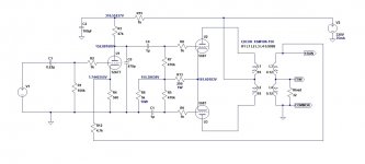
Earlier in this thread the attractive characteristics of 12AT7 were mentioned. I've been thinking about tube headphone amps lately. I have a pair of Edcor XSM10K:150 OPTs I want to build something around. I'll probably use a 5687 (similar to 6N6P) per side, the two triode sections in push-pull, since I've collected too many of those tubes. I was looking at a common cathode voltage amp in front, to give some gain for NFB. I was planning to use a 6SN7 to make a sort of 'Taj Mahal' look (the big, fat, octal 6SN7 with two little 5687s on either side). But when I made a simulation using a 12AT7 and wrapped about 10 to 12dB of gNFB around it, I came out with amazing numbers (like 0.05% THD at 1V RMS out into 32 ohms), with a harmonic signature that looks like an SE amp (H2 dominant, H3 15 to 20dB down from that). Have a look, see what you think.
I'm not in the same league as you guys, so I'm sure there are massive improvements to be made here.
I'm not in the same league as you guys, so I'm sure there are massive improvements to be made here.
Attachments
Last edited:
There are a few audio amplifier schematic with ECL84, but I haven't found any with ECL85. It should be equivalent to the even cheaper and more popular 6F5P but I don't know if it is true. There are several 6F5P amplifier schematics.
ECL85 pentode curves don't look that great, but triode curves look good. Should make a nice PP flea power.
Attachments
But when I made a simulation using a 12AT7 and wrapped about 10 to 12dB of gNFB around it, I came out with amazing numbers (like 0.05% THD at 1V RMS out into 32 ohms), with a harmonic signature that looks like an SE amp (H2 dominant, H3 15 to 20dB down from that). Have a look, see what you think.
Can you sim it with an added 12AT7 concertina, so that both grids are driven? Would be interesting to compare distortion spectra/harmonics.
- Status
- This old topic is closed. If you want to reopen this topic, contact a moderator using the "Report Post" button.
- Home
- Amplifiers
- Tubes / Valves
- Can we discuss PP Flea amps for hi-fi