Hi folks,
I'm new to this community, so please bear with me if I made myself sound like a newbie (which I am...)
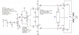
Currently working on my first DIY tube amp project, had a big picture figure out but just running into some detail questions. I have the schematic attached below, with some notes on there about how I pick the numbers, calculations, and all that stuffs
Note: The drawing app does not have a UL type output transformer, so I used two to represent it... I'm sure you'll get the idea. Second, some how it doesn't allow me to use the cathode pins of the KT88s, so I used arrows instead.
The design idea is based on the site below: Valve Amps: Output stage
I'm trying to get it to have 75 to 100W power/channel
With all that said, I questions:
1. How do I pick the primary impedance for the transformer?
2. How to calculate the voltage amplified after the power stage (or even each stage)
Also if anyone have any comments or see anything that could be potential issues in the schematic, I'm open to any of them")
Thanks!
I'm new to this community, so please bear with me if I made myself sound like a newbie (which I am...)
Currently working on my first DIY tube amp project, had a big picture figure out but just running into some detail questions. I have the schematic attached below, with some notes on there about how I pick the numbers, calculations, and all that stuffs
Note: The drawing app does not have a UL type output transformer, so I used two to represent it... I'm sure you'll get the idea. Second, some how it doesn't allow me to use the cathode pins of the KT88s, so I used arrows instead.
The design idea is based on the site below: Valve Amps: Output stage
I'm trying to get it to have 75 to 100W power/channel
With all that said, I questions:
1. How do I pick the primary impedance for the transformer?
2. How to calculate the voltage amplified after the power stage (or even each stage)
Also if anyone have any comments or see anything that could be potential issues in the schematic, I'm open to any of them
Thanks!
Attachments
1. starting with the datasheet figures for UL operation is always a good idea.With all that said, I questions:
1. How do I pick the primary impedance for the transformer?
2. How to calculate the voltage amplified after the power stage (or even each stage)
2. simple, just Vo = A x Vin, where A is the gain of the stage, which you can calculate/estimate based on the operating conditions.
There is no NFB. Is that your intention?
1. starting with the datasheet figures for UL operation is always a good idea.
2. simple, just Vo = A x Vin, where A is the gain of the stage, which you can calculate/estimate based on the operating conditions.
There is no NFB. Is that your intention?
Right there should be a NFB, shown in the attachment
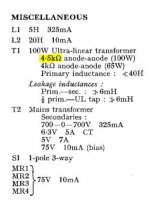
Also I just found this datasheet
https://frank.pocnet.net/sheets/084/k/KT88_GEC.pdf
In the PP, fixed bias, UL connection (which is what I have right now), it says Zout range from 6.5k to 7k ohm, I assume that means the primary impedance of the OPT. But there's also RL(a-a) range from 4k to 4.5k ohm.
And if you scroll down, there's a PP 100W schematic, and they use a 4.5k ohm transformer. So... I'm little confused over here....
Attachments
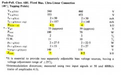
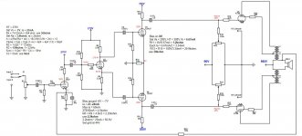
Zout isn't the same thing as RLa-a. You are interested in the RLa-a, so 4.5k will do. The NFB as drawn is incorrect, the signal is shunt to ground by the cathode bypass capacitor. See http://copyright.lenardaudio.com/laidesign/images/a14/a14_negative-feedback.gif for an example for the correct connection (which still requires adjustment).
I did find some 5k and 4.2k transformers but no exact 4.5k ones. I assume that would slightly alter the output power but shouldn't be anything serious
So for the NFB, could that be fixed by simply removing the cathode bypass cap? or is there other way of connecting the NFB loop while keeping Ck?
So for the NFB, could that be fixed by simply removing the cathode bypass cap? or is there other way of connecting the NFB loop while keeping Ck?
C2 should be connected to the junction of R3 and anode of V1. I'd also look into direct coupling V1 to V2 in order to eliminate the cap and bias divider.
You might also look into substituting a LTP input stage for the grounded cathode+cathodyne. See the well-documented AB input stages here for inspiration: http://www.diyaudio.com/forums/tubes-valves/133034-6l6gc-ab2-amp-68.html#post4684906
You might also look into substituting a LTP input stage for the grounded cathode+cathodyne. See the well-documented AB input stages here for inspiration: http://www.diyaudio.com/forums/tubes-valves/133034-6l6gc-ab2-amp-68.html#post4684906
Do you mean even better documented than the Williamson amplifier?See the well-documented AB input stages here for inspiration:
To get 75 watts output in UL mode with KT88's, 6550's or equivalent, you'll need approximately 525V to 550V at the center taps of the output transformers with 4.3K to 5K primary impedance transformer and with 33% to 43% UL taps.
But the devil is in the details as they say. If this is your first attempt at scratch designing and building a power amp, I might suggest a simpler and lower wattage type for starters. I'm quite fond of my 6V6 amp that I re-engineered from a Motorola console. Twelve glorious watts!
But the devil is in the details as they say. If this is your first attempt at scratch designing and building a power amp, I might suggest a simpler and lower wattage type for starters. I'm quite fond of my 6V6 amp that I re-engineered from a Motorola console. Twelve glorious watts!
Do you mean even better documented than the Williamson amplifier?
hi
can explain about Williamson amplifier different to other pentode amps ?
nfb ?
pentode use ?
The Williamson amplifier is arguably the first "modern" tube amp design, first published in Wireless World back in 1947. Definitely pentode, as Williamson detested the "ultralinear" connection. There are literally hundreds of variants/clones of the Williamson amplifier since then, which you can find via a bit of Googling. Have fun!

first audio project should be push pull and made by popular hifi tubes . dont use compectron and tv h out like el509.....transmitter tube .....dht tubes like 2a3....6b4g...vt25...300b..
but 6l6gc.....el34....6v6.....el84....6550...kt88...kt66... ecl86.. are easy to use .never use ac transformer in place of output chock .tube rectifier is safe for beginners amps .
I've built seven amps using Triad VPT series power transformers as OPTs, including a KT120 triode push pull that makes 45W, 5W class A limit. If you use individual bias controls in fixed bias, an automatic bias board like the ones Pavel sells at audioamp.eu or either CCS cathode biasing or a garter circuit, they work very well. They can tolerate a slight DC unbalance, too.
I would suggest for a first time build to use cathode biasing for the simplicity of it. You can always modify it for fixed bias at a later time.
The Acrosound 6L6 build was my first build, and it sounded great from the first power up. http://www.keith-snook.info/amplifier-hifi-schematics/Acrosound%206L6%20Rebuild.pdf
If you build the above, I suggest separate biasing resistors (R14) for each output tube. Simply double the value of the single resistor to achieve the same bias point. Bypass each one with it's own capacitor. I prefer 330uF instead of 100uF.
Last edited:
Do you mean even better documented than the Williamson amplifier?
Touche. But try asking Williamson for help if you don't understand something about his write up
George, on the other hand, will probably chime in on this thread at some point if you ask him to or not!- Status
- This old topic is closed. If you want to reopen this topic, contact a moderator using the "Report Post" button.
- Home
- Amplifiers
- Tubes / Valves
- First DIY tube amp