thanks for your good advice.The Williamson amplifier is arguably the first "modern" tube amp design, first published in Wireless World back in 1947. Definitely pentode, as Williamson detested the "ultralinear" connection. There are literally hundreds of variants/clones of the Williamson amplifier since then, which you can find via a bit of Googling. Have fun!
more than 10 years i searching google and working on hifi tubes amps ..guitar amps....studio mic preamp ...every day .i have 5000 famous nos tubes and 15000 other like 6sj7...6sh7..ef800 ....
williamson is not clear design.
when people came here to find good circuits or kits ...should fined best result . please look at blow :
is this classic and standard circuit for push pull ?
Switchable Single-Ended, Push-Pull Guitar Amp
for first diy output power is important .usually new diyers speaker is low sensitivity.
classic push pull with common phase splitter is very good chois .
push pull can decrease hum easily.


What is not clear? What do you considered "best result"?williamson is not clear design.
when people came here to find good circuits or kits ...should fined best result
It's just a simplified output stage for illustration purpose, what of it?is this classic and standard circuit for push pull ?
If you read any article on the Williamson amplifier, you would not be asking this question.is this williamson ?
If your point is that there are easier amplifiers for first time builders, then yes, Williamson isn't the easiest. Happy now?
")
can halp from googling for answer ?
do you compare sound quality in this simple topology with classic push pull your self?It's just a simplified output stage for illustration purpose, what of it?
First, let me apologize, I mistakenly took the above diagram as a conventional PP output stage but after another look, it's not one at all, but rather a self-splitting type, which was commonly found in cheap radios/consoles back in the day, and some guitar players seem to like it too. The biggest disadvantage of the self-splitting output stage is that it only operates in Class A, which wastes power, and the biggest "advantage" is its lower cost - since a separate phase inverter stage is no longer needed.
Post 21 schematic is an attempt to make a push pull output into 'sort of a single ended' output.
You will notice that the cathodes are Not coupled to each other, there is No self inverting in this stage (the cathodes are connected to ground through their individual respective cathode resistors.
The "pull" stage control grid is connected through a grid stopper resistor to ground. That makes this un-driven pentode stage into a constant current source. the current merely balances the quiescent current of the "push" stage, so that a push pull transformer without air core can be used as a 'single ended' output.
In order to be a self inverting stage, the cathodes have to be tied together, and then through a suitable Common resistor to ground, or better yet through a current source to ground.
Last edited:
The Williamson amplifier is arguably the first "modern" tube amp design, .... Definitely pentode, as Williamson detested the "ultralinear" connection. ...!
Um, IIRC, the Williamson was "triode" power stage. By necessity, it used triode-strapped KT66 (beam tetrode, patent-evading pentodes) (good big triodes were fading from the scene), but was triode operation.
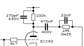
Yes, they are for NFB compensation, but those are not on your schematic.Well, I was more interested in these part of the circuit (in the attachment)
Looks like some kind of compensator? thought I might saw similar ones somewhere
guitarnerd,
Where did you get those schematics in post # 33? I do not remember seeing those. They almost look like some passive frequency response networks for something like phono preamps, or similar.
Take a look at the dyna stereo 70:
dyna st 70 schematic - Google Search
It has 2 negative feedback compensation networks:
1. A series RC (82pF 18kOhm) dominant pole from the input Pentode plate to ground (often found in amps). The dominant pole on your amplifiers may be your output transformer.
2. A capacitor from the screen of the bottom output pentode (Ultra Linear tap) back to the input Pentode cathode circuit (very unusual). Instead, these compensation caps are more often connected from the output transformer secondary (across the main negative feedback resistor) to the input pentode cathode circuit.
The main feedback resistor is 1k Ohm from the output transformer 16 Ohm tap to the input pentode cathode circuit.
With negative feedback that comes from the output transformer secondary to the input cathode, there are usually a self bias resistor and bypass cap in parallel from the cathode, with the bottom of that network to another resistor to ground. The negative feedback is applied to the junction of the bottom resistor and the self bias network.
Last edited:
post...22guitarnerd,
Where did you get those schematics in post # 33?
I do not remember seeing those.
.
post....23
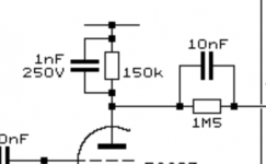
Well, I was more interested in these part of the circuit (in the attachment)
Looks like some kind of compensator? thought I might saw similar ones somewhere
if have more gain can use this kind of passive circuit for high frequency response .
- Status
- This old topic is closed. If you want to reopen this topic, contact a moderator using the "Report Post" button.
- Home
- Amplifiers
- Tubes / Valves
- First DIY tube amp