Perhaps I should try grounding one heater lead?
Sorry, I didn't mean to suggest trying that. Some very old guitar amps (1950s Fenders, etc.) used a two-wire AC heater hookup, with one wire of the heater winding at 6.3VAC and the other one grounded. I would *not* recommend using it that way, not at all. I was hoping you hadn't done that; glad to see it's not used like that.
--
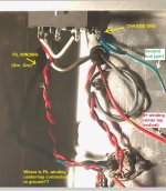
I took the liberty of marking up the photo of your layout. I hope you don't mind.
I still can't tell where you have the filament (heater) supply grounded. In the photo it looks to me like it's floating. I'm probably just missing something.
The green wires coming from the power transformer should be the 6.3VAC secondary winding. If that secondary has a center tap, it will usually be a third wire with green/yellow insulation. I don't see that coming from your power transformer. From what I can see, you're required to make an artificial center tap for this filament supply. But again, I might be missing something. Can you clarify?
--
When I elevated my heater filament supply, I calculated the voltage divider resistor values to give me a +30V DC point. I got +25V (oops). Still works fine.
--
Edit to add: Where it says "CHASSIS GND", the green wire should be connected to a solder tab on a washer on a good bolt screwed tight into the metal chassis, with a star washer digging into the metal. You want solid electrical contact there for the ground bus. If that connection is loose or has any residual resistance at all, you could be introducing noise there.
If you're using Hammond 270BX as your power transformer (http://www.hammondmfg.com/pdf/EDB270BX.pdf) then the 6.3VAC secondary does not have a center-tap, and you are *required* to create an artificial center tap for it.
--
Attachments
Last edited:
Thanks rongon. Actually it’s floating. There is no C.T. on the 6.3v winding. (PT data sheet here: http://www.hammondmfg.com/pdf/EDB269EX.pdf)
So I need to add the artificial C.T. and pick a resistor value to take B+ to 30V, attach the C.T. there, and then add a resistor (of what value?) and bypass cap to ground?
So I need to add the artificial C.T. and pick a resistor value to take B+ to 30V, attach the C.T. there, and then add a resistor (of what value?) and bypass cap to ground?
Last edited:
Actually it’s floating.
I'm 95% sure that has to be the source of the hum/buzz.
You need to decide where you'll be dropping your DC voltage from to make your +30V 'virtual ground.'
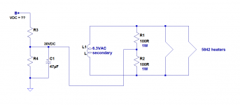
The schematic shows the circuit for elevating the heater supply.
R3 and R4 make the voltage divider.
Calculate values of R3 and R4 to give you +30V DC at the junction of those two resistors.
If the B+ is 300V, then something like R3 = 220k and R4 = 27k should get you close enough. These need to be 1W rated resistors. Metal oxide or carbon film would be fine.
C1 needs to be large enough to shunt all AC frequencies to ground. You can make it arbitrarily large, to be safe. 10uF would be enough.
Attachments
Last edited:
So...
B+ = 149V
Total current draw = 54mA
149 - 30 = 119V needs to get dropped
119/0.054 = 2203.7
R3 = 2.2K
The other 30 volts -- 30/0.054 = 555
R4 = 550 ohm or 560 ohm, whatever's the closest standard value
C1 ~ 10uF (your drawing has 47uF) at minimum 35 volts (would probably go 50V or more)
B+ = 149V
Total current draw = 54mA
149 - 30 = 119V needs to get dropped
119/0.054 = 2203.7
R3 = 2.2K
The other 30 volts -- 30/0.054 = 555
R4 = 550 ohm or 560 ohm, whatever's the closest standard value
C1 ~ 10uF (your drawing has 47uF) at minimum 35 volts (would probably go 50V or more)
You don't want to drop 54mA across your voltage divider resistors. That would be a waste of power transformer current, and those resistors would run hot.
149V * 0.054 = 8W dissipated <-- OUCH!!
This might be helpful -- Voltage Dividers - learn.sparkfun.com
Vout = (R4/R3+R4)Vin
Step 1:
We want the resistor values to be as high as we can get away with (high impedance), so that we can drop those volts with a minimum of current drawn across the voltage divider resistors.
For most tubes, the maximum resistance between cathode and heater is stated to be 47k ohms (or thereabouts). Let's pick 22k, because it's an easy value and it's about half the max value of 47k. So, R4 = 22k
Step 2:
Your B+ (or Vin) = 149V
Let's figure out what resistance is required to drop 149V from B+ to ground, drawing 1mA through R3+R4.
149/0.001 = 149,000
That's R3+R4 = 149k
Since we've already chosen R4 = 22k, and we know we want to make Vout = 30V, we'll want to drop 30V across 22k. How much current needs to be drawn across R4 (22k) to get us 30V?
30V/22k = 0.0013636 A
That's 1.364mA
We know Vin is 149V. That means we want to drop 149-30 = 119V across R3. What value must R3 be?
119V/0.001364 = 87.24k
Hmmm. Not a standard value. Yeah, that's the way it goes. Let's take a wild guess and scale up our values to standard resistor values. How about R3 = 100k and R4 = 27k?
R3+R4 = 100k + 27k = 127k
149V/127,000 = 0.001173 = 1.17mA
What voltages will we get?
R3 will drop 100k*1.17mA = 117V
R4 will drop 27k*1.17mA = 31.59V
Close enough!
How much wattage (heat) will each resistor need to dissipate?
For R3 dropping 117V at 1.17mA, 117*0.00117 = 0.13689, so better make R3 at least a 1W rated part
For R4 dropping 31.6V at 1.17mA, 31.6*0.00117 = 0.036972, so R3 can be a 1/2W rated part
For C1 (in parallel with R4), 10uF will be fine, 47uF will also be fine. I'd find a minimum 100V rated part, but I guess you could get away with 63V.
That's how I'd do it. I'll bet somebody else has a more efficient method.
--
Last edited:
Regarding C1, you want it to shunt (filter out) all AC frequencies down to below 1Hz.
The fc (-3dB rolloff frequency) of the RC filter needs to be <1Hz.
fc = 1/2piRC
R in ohms, C in Farads, so uF = F*0.000001
To find fc for R = 27,000 and C = 10uF (0.00001 F):
2piRC = 2 * pi * 27,000 * 0.00001 = 1.69646
1/1.69646 = 0.5895 Hz
That'll do nicely.
--
Since for power supply decoupling we usually want to filter down to below 1Hz, an easy rule of thumb for figuring out values for the RC low pass filter is to make the product of R (in ohms) and C (in uF) > or = 150,000.
So if you have a 1k resistor as the decoupling resistor for your power supply, 150k/1k = 150, so choose C = 150uF.
You can reduce that to 100uF and still be filtering down below 2Hz, which is almost always good enough.
In the case of our voltage divider with R4 = 27k, that would be 150k/27k = 5.556, so choose C = 5.6uF or higher.
--
Last edited:
Thanks rongon. I bookmarked that page. So, the calculator there results in a Vout of exactly 30V using the resistor values I derived above. I tried to check my method against the formula at the tutorial you pointed out but am unsure how to manipulate it to solve for R1 (since I guess we know R2 would have to be 555 ohm to set Vout to 30V).
But I will find tutorials to help with that.
In the meantime, my preliminary searching found this page featuring a calculator that allows you to put in any known values to obtain the rest. Totally "cheating" but very useful.
Voltage Divider Calculator
Anyway, I've got a 2.2K 25W that will do for the top of the divider, but will have to get the 550-560R 5W and 100R 1-2W at Affiliated tomorrow.
Using the fc formula with a 560R resistor, 10uF gets me about 28Hz, 47uF gets 6 Hz, 100uF gets 2.8 Hz, 160uF gets 1.8 Hz, 330uF gets 0.86 Hz.
Last edited:
>>> WARNING: There is a safety issue here. Please do not proceed until you have done the following: <<<
Using the values you calculated, calculate the heat (power in watts) dissipated by those resistor values.
P = E*I (or VA)
Also, calculate the fc of an RC low pass filter comprised of R = 560 ohms and C = 10uF. Remember that you want the low pass filter to have an fc of lower than 2Hz, or lower than 1Hz if you can get there easily.
Last edited:
I've got a 2.2K 25W that will do for the top of the divider, but will have to get the 550-560R 5W and 100R 1-2W at Affiliated tomorrow.
Why on earth would you want to dissipate 8 watts of heat when you could just as easily dissipate well under 1 watt and get the job done much better and much cheaper?
Using the fc formula, 10uF gets me about 28Hz, 47uF gets me 6 Hz, 100uF gets me 2.8 Hz.
If you insist on dissipating 8 watts in your voltage divider resistors, you'll need to keep that capacitor physically far away from the resistors, since they will be running HOT.

Really, a 25W resistor is large and expensive, and will be running quite hot, even dissipating 'only' 6.5 watts of heat.
Look at the resistive voltage dividers others have used for lifting their heater supplies. It's always good to check out what experienced builders do. Don't take my word for it.
--
Here's a good general reference for basic tube amp design:
The Valve Wizard
Heater Elevation
Elevation means referencing the heater supply to a DC voltage other than ground or zero volts. The heaters still operate at 6.3V or whatever, but this floats on top of the elevation voltage. Some valve stages such as cathode followers require the heater supply to be elevated to avoid exceeding the valve's Vhk(max) rating. But even when not explicitly needed, elevation can reduce hum in AC-heated circuits by reducing or saturating the leakage current between heater and cathode.*
The DC voltage is applied to a transformer centre tap, artificial centre tap, humdinger, or whatever reference connection the heater supply would normally have.
The elevation voltage can be taken from a potential divider across the HT (it doesn't matter where you position the divider), and an elevation voltage around 30 to 60V is typical. The divider should have a fairly high resistance so as not to waste current, although the lower arm (R2) should not be excessively large or Rhk(max) may be grossly exceeded, so it is advisable not to make it greater than 100k. The elevation voltage should be decoupled/smoothed with an arbitrarily large capacitor (C1), say 10uF or more.
Emphasis added.
--
Last edited:
Well, I didn't think that was up to me. There's 54mA of current on the B+ rail, so I figured all the resistance values to get the desired voltage -- and therefore the watts dissipated -- would be fixed by physics.Why on earth would you want to dissipate 8 watts of heat when you could just as easily dissipate well under 1 watt and get the job done much better and much cheaper?
But playing around with that calculator, I now see I can easily do it with -- for instance -- 100R and 25R resistors of about a watt each.
But 25R becomes difficult to get a capacitor for 1Hz or lower, so I'm starting to see the game now.
Electricity is weird, man.
Last edited:
Electricity is weird, man.
Ohm's Law. It all follows Ohm's Law.
https://www.electronics-tutorials.ws/dccircuits/dcp_2.html
But playing around with that calculator, I now see I can easily do it with -- for instance -- 100R and 25R resistors of about a watt each.
"Georg Ohm found that, at a constant temperature, the electrical current flowing through a fixed linear resistance is directly proportional to the voltage applied across it, and also inversely proportional to the resistance. This relationship between the Voltage, Current and Resistance forms the basis of Ohms Law."
If you drop 149V across a total of 125 ohms, it will require 1.192 Amperes of current across the resistors. (Ohm's Law!)
Power is voltage times current, so 149V * 1.2 A = 177.6 WATTS (!!!)
I think maybe you confused amps (current) with watts (power).
Voltage (E), current (I), resistance (R) exist in a relationship where one is proportional to the others. (Ohm's Law) -- For instance,
Let's say we want to drop 150V to 0V.
Ohm's Law says E = I x R
That also means R = E/I and I = E/R
So, we can find what current will be drawn across a resistance when that resistance is installed between +150V and 0V. Let's put 100k ohms in there.
I = E/R, or Current = 150V divided by 100k ohms
150/100,000 = 0.0015 amperes or 1.5mA
(one milliampere = one thousandth of an ampere)
Our 100k ohm resistor will drop 150V across it, with 1.5mA (0.0015A) of current drawn through it (from ground to +150V).
How much power is being dissipated in that 100k resistor dropping 150V?
Remember that P = E x I (power equals voltage times current), so
150V x 0.0015A = 0.225W
That's reasonable. Less than a quarter of a watt.
__________________________________________
BUT, if we reduce that resistance to only 100 ohms, then
150/100 = 1.5A (1.5 amperes)
That's a LOT more current. Notice that the 100 ohm resistor is still dropping 150V. However, it now has to draw a lot more current through it to drop that same number of volts.
Ohm's Law at work.
How much power must be dissipated in that 100 ohm resistor dropping 150V?
Again, P = E x I, so
150V x 1.5A = 225 watts
TWO HUNDRED AND TWENTY FIVE WATTS!!
Yet both resistors were dropping the same voltage (150V).
Ohm's Law.
Ohm's Law.
Ohm's Law.
Ohm's Law.
--
Last edited:
Ha! I think we've been writing past each other. I just read the rest of your post #108, where you very thoroughly and methodically (and graciously) solve the problem, but which only contained a link to a tutorial when I first saw it (and which spawned the rest of my posts following, which I also continuously revised).
Since the B+ rail has 54mA on it from the tubes draw, I assumed that 54mA would be headed to ground with the voltage divider and would define the current running through it. I think maybe I should not do electronics when it's late and I'm tired.
I've got a 100k 1W, 27k 4W (over-spec'd, I know), and a 10uF 100V, and should be good to go. Too tired and will tackle it tomorrow.
Last edited:
This place has a bunch of simple online calculators, and a windows program that can be downloaded to do all of the calculations locally and offline. Very handy.
Electronics 2000 | Downloads - FREE software including Electronics Assistant & EPE Index
Win W5JAG
Electronics 2000 | Downloads - FREE software including Electronics Assistant & EPE Index
Win W5JAG
So I realized that since my B+ comes from the final, separated PS legs, it would be a bad idea to tap the elevation circuit from just one channel. So I'm going to take it from C3, just before the split, which is at 182V.
Using a standard resistor value for R4, I could do:
R4 -- 30V/27k = 1.1mA of current @ 0.033 watt
R3 -- 152V/.0011 = 138.2k @ 0.1672 watt
138k is non-standard. If I use a standard 130k in that position, Vout is 31.3V, which should be fine.
Of course, the added 1.1mA of current draw will raise voltages a little across the board, but should still be safe to run the 5842s and I can tweak from there.
So I realized that since my B+ comes from the final, separated PS legs, it would be a bad idea to tap the elevation circuit from just one channel. So I'm going to take it from C3, just before the split, which is at 182V.
Using a standard resistor value for R4, I could do:
R4 -- 30V/27k = 1.1mA of current @ 0.033 watt
R3 -- 152V/.0011 = 138.2k @ 0.1672 watt
138k is non-standard. If I use a standard 130k in that position, Vout is 31.3V, which should be fine.
I don't think there's anything magical about the +30V. You could raise the heater ground to +20V, or +25V, or around there somewhere, and still get the benefits you're after.
Using standard resistor values, keeping R4 = 27k, and doing a little math for fun...
From Vin = 152V,
R3 = 150k
R4 = 27k
R3+R4 = 150k+27k = 177,000 ohms
I = 152V/177,000 = 0.86mA
Vout = 27,000 x 0.00086 = 23.2V
R3 = 120k
R4 = 27k
R3+R4 = 120k+27k = 147,000 ohms
I = 152V/147,000 = 1mA
Vout = 27,000 x 0.0012 = 27V
R3 = 100k
R4 = 27k
R3+R4 = 100k+27k = 127,000 ohms
I = 152V/127,000 = 1.2mA
Vout = 27,000 x 0.0012 = 32.3V
R3 = 82k
R4 = 27k
R3+R4 = 82k+27k = 109,000 ohms
I = 152V/109,000 = 1.39mA
Vout = 27,000 x 0.0012 = 37.65V
For 5842 or 417A, the maximum heater-cathode voltage is specified as 55V. Just keep the Vhk well below 45V and you should be good. So for R4, take your pick of 82k, 100k, 120k, or 150k, whatever you have in stock in 1/2W or 1W. Any of those should work fine.
--
Of course, the added 1.1mA of current draw will raise voltages a little across the board, but should still be safe to run the 5842s and I can tweak from there.
Actually, increasing the current draw will lower the voltages just a little.
There will be a little more voltage dropped across the DCR of your power supply choke or decoupling resistor (in series with B+).
It's that Ohm's Law again.
--
Last edited:
Oops. I made a mistake. Your B+ tapping point is at 182V, not 152V. My bad. But the math is the same.
You could still use 150k or 120k for R3 and all would work out fine.
R3 = 150k, Vout = 27V
R3 = 120k, Vout = 33.4V
R3 = 100k, Vout = 38.7V
Either will work.
But
R3 = 82k, Vout = 45V (I'd say don't go that low for R3)
--
You could still use 150k or 120k for R3 and all would work out fine.
R3 = 150k, Vout = 27V
R3 = 120k, Vout = 33.4V
R3 = 100k, Vout = 38.7V
Either will work.
But
R3 = 82k, Vout = 45V (I'd say don't go that low for R3)
--
Last edited:
We're in business! Heater elevation of 30V works just fine (I found 137K and 27K resistors at Affiliated), as did 25V and 22V. I left it at 30. It sounds great.
I have to button up the monster and turn it over, and will post final build pics in a little while.
Thanks to everyone who was so generous with their time and patience as I muddled through this.
I have to button up the monster and turn it over, and will post final build pics in a little while.
Thanks to everyone who was so generous with their time and patience as I muddled through this.
- Status
- This old topic is closed. If you want to reopen this topic, contact a moderator using the "Report Post" button.
- Home
- Amplifiers
- Tubes / Valves
- 5842 Headphone Amp