I installed the EZ81, which results in zero audible hum. Maybe the indirect heating helps there. I made some measurements and listening tests.
With 100 ohm Rk and 1.8k wirewound cement dropping resistor:
B+ 156.7
Va 149.7
Vk 2.15 (21.5mA)
3.17 watts
With 62 ohm Rk and 1.8k dropping resistor:
B+ 140.3
Va 131.4
Vk 1.59 (25.6mA)
3.3 watts
With 62 ohm Rk and 820 ohm wirewound cement dropping resistor:
B+ 155
Va 145
Vk1.77 (28.5mA)
4 watts
Max dissipation of 5842 is 4.5 watts. Too close?
I need to plot the loadlines for comparison. The music has more body and better tone/detail with the higher current configurations. It's very pleasing but I'd like to find a configuration that gives more "air" and "space."
Also I have a pair of 7C5 (loktal 6V6) that would give about 1 watt triode strapped. Would that be worth trying in a headphone setup?
Last edited:
Not to get too far off topic, but with these Raphaelite OPTs that have configurable 8 or 32 ohm secondaries, I could make a versatile speaker and headphone amp with 7C5 or 6CU6. Maybe even with other tubes in my stash like 6K6 or 6K7. It could have switches for pentode/triode and headpone/speaker. In triode mode they’d put out 1-1.5 Watts, which is plenty for my Grado SR125s.
I’m wondering whether I could run them in pentode or tetrode mode, which would put out about 4-4.5 Watts. I see no power handling specs for my Grado SR125 so, assuming signal level is kept within limits, would I fry my cans with that kind of power?
I’m wondering whether I could run them in pentode or tetrode mode, which would put out about 4-4.5 Watts. I see no power handling specs for my Grado SR125 so, assuming signal level is kept within limits, would I fry my cans with that kind of power?
I would worry more about frying your ears.
You can make a simple 32 ohm attenuator pad for the headphone output to reduce the power to the 'phones and your ears, while allowing the tube to run at a speaker power level / operating point.
Look for search terms like "L Pad" "T attenuator" "Pi attenuator" maybe others. There are online calculators for all of them. L Pad's might be the best choice for audio.
I "think" 7B5 is the loctal 6K6. There is also a 7A5, but I'm not sure what it types to. I haven't used loktals at all.
Win W5JAG
No.
It will provide a fixed attenuation at a constant impedance, in your case, 32 ohms.
You would put the attenuator in the 32 ohm secondary of the OPT, before the headphones.
You just decide on how much attenuation you want. You would probably want at least 20 dB, depending on what you build.
Win W5JAG
Cool. I'm definitely going to try it.
Tried a higher voltage/lower current config of the 5842, using the 360 ohm dropping resistors in the PS and 100 ohm carbon comp Rk.
B+ 177
Va 168
Vk 2.45
24.5mA
4 watts
I like this combo. Might try a larger Rk to raise voltage/lower current and see what happens.
I also still want to try paralleling my vimtage 3uF oil caps with the final PS electrolytics. Also, want to hear into the recording more, which could be source/phones too. I'm listening to Apple lossless files on iTunes that were ripped from CD. Need a new volume pot if I'm going to play directly from CD. Better source and something like the 32 ohm Beyerdynamic DT-880 could help.
Last edited:
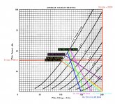
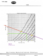
Here are load lines of what I've tried so far. I followed Broskie's method, where you take the minimum current level (where it stops being linear) from the tube datasheet graph, subtract that from the quiescent current, and add the difference to it at the 0V grid line. Then draw a line toward the bottom of the graph such that it passes through the intersection of the plate voltage and quiescent current.
In the Raytheon datasheet, it looks to me like linearity breaks up at about 5mA, so I subtracted that from each result and then added the difference for the 0V grid point. Am I doing that right?
In the attached chart, the yellow, green, dark blue, light purple, and dark purple lines are the ones I reported sounding best.
Attachments
I've never seen load lines done that way. The way I learned is...
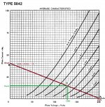
1) Take your B+ supply voltage (not the voltage at the plate/anode). On the plate curves (as above), mark that voltage on the bottom margin of the graph (the horizontal, or x axis). Let's say 200V. That's point "A" on the attached image.
2) Take the value of the plate/anode load resistor (Rp).
Divide the B+ voltage by the value of Rp. Let's say Rp is 5k ohms.
200V/5,000 ohms = 0.04A (40mA)
Mark that result on the left side of the graph (the vertical, or y axis). That's point "B" in the image.
3) Draw a straight line from point "A" (200V at the far right of the horizontal axis) to point "B" (40mA on the vertical axis). That's your load line. That's the brown line on the attached image.
4) Let's say you're happy with that, and you want to employ grid bias of -1.5V. Find the grid curve labeled -1.5V and mark where that -1.5V curve meets the load line, at point "C" in the image.
Note the green lines I drew from point C.
- Point C is at +128V on the horizontal (plate volts) axis.
- Point C is at about 15mA on the vertical (plate current) axis.
That means for a typical 5842:
B+ = 200V
Vp = 128V
Vg = -1.5V
ip = 15mA
Rp = 5k ohms
____________________________________
The maximum plate current (ip) is stated as 38mA, but that's actually relative. You can't assume that just because your 5842 is drawing less than 38mA plate current that it's within its safe operating area. What's important is the maximum plate dissipation. That's how much heat the plate can dissipate before melting, measured in watts. Max plate dissipation for the 5842 is stated to be 4.5W.
Watts is (approximately) voltage (in volts) times current (in amperes).
If your 5842 has plate voltage of 128V and plate current of 0.015A (15mA), then the plate dissipation is:
128V * 0.015A = 1.92W
That's safely within the limit.
Let's say you try to draw 35mA plate current through the 5842, with 150V plate voltage.
150V * 0.035A = 5.25W
That's 0.75W over the limit. That will likely burn up the 5842. Even though the plate voltage is less than the stated maximum (200V) and the plate current is less than the stated maximum (38mA), the plate dissipation of over 5W is much more than the absolute maximum rating of 4.5W.
--
Attachments
Thanks Rongon. I found the same method at the Valve Wizard but hadn’t tried it yet. So Rp is actually, in this case, the primary impedance of the OPT, not its DCR. That’s something I was wondering about in the Valve Wizard’s write-up.
I did calculate the wattage to make sure that was below max, which you’ll see in the posts above.
Yesterday I tried a lot of different operating points and found that I preferred lower voltages and higher currents, with dissipation in the 3-3.5 watt range. When I get a chance later I’m going to graph the load lines of my preferred configurations using the method you outlined. So thanks again for that.
Getting back to this, I think I'm zeroing in on a final design.
Lots of activity over the past few weeks:
* Tried a split rail power supply, with the channels split after the 47uF cap that connects to the rectifier. Some decent results with lower voltage & higher current as reported above, but a little noisier and less coherent. Switched back to single rail supply (chokes in series), and it's quieter, much more coherent, controlled, detailed, with nicer soundstage. So, single rail it will be.
* I ended up buying a pair of vintage 25uF oil caps at my favorite electronics store, so now the PS chain is:
EZ81 -- 47uF electrolytic -- 10H -- 100uF electrolytic (JJ) -- 10H -- 100uF electrolytic -- 1.3K -- 25uF oil + 3uF oil in parallel.
I just ordered a 50uF oil motor run for the input cap in the final build. I *really* like what oil caps in the PS do for the sound.
* After switching back to single rail and trying more configurations, my favorite op point so far (presence! detail! space! tone!) is:
B+ 155V
Va 145V
Vk 1.75V
29.17mA
4.18 watts
However, at 93% of max plate dissipation, I'd rather back that down a little for the sake of tube life.
* So, the following configuration is about equally good but with less dissipation:
B+ 149V
Va 139V
Vk 1.63V
27.17mA
3.73 watts
That's 83% of max dissipation, and after about 45-60 minutes of listening the operating condition settles to about 77% of max dissipation.
This strikes me as a good compromise, unless other members here think that 83%-77% is running the tube too hard.
Last edited:
Sounds like an enjoyable build. I'm surprised that a single B+ feeding both channels sounds better than individual decoupling for each channel. I'll have to try that in my similar HP amp.
Did you do a frequency sweep to see how low the amp goes in the bass?
What OPTs are you using?
I don't think 77% of max dissipation is a problem.
Did you have to find matched pairs of 5842 tubes to get good balance channel to channel? That's the only hassle I've run into with my amp using high gm RF tubes. Curious if 5842 are more consistent than the tubes I'm using.
I have a matched pair of NOS JAN Raytheon 5842 from my first project 3 years ago-- the Tubelab SE. Volume balance is just fine per channel.
I'm using Grado SR125 (32 ohm) cans with Raphaelite OP5.5K5A OPTs (5.5K: 8 or 32 ohm, 5W) from this seller on eBay (Raphaelite 5W single-ended output transformer OP5.5K5A 6V6 EL84 sealed | eBay). Websites show the primary to be either 5K or 5.5K. I've written to the seller for clarification but am assuming it's 5.5K because they advertise these OPTs for use with 6V6 and EL84 and have two other OPTs designated for those tubes that have 5.5K primaries (also it's in the product name).
Some of the improvements I've been hearing could be due to OPT break-in, but I'm really starting to like these. They do a good job of reproducing detail and other nuance, and are sounding very clear indeed as documented below.
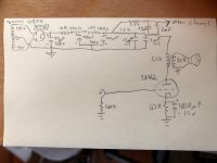
The channels split after the second 100uF cap (it's a JJ 100uF + 100uF). I drew out a schematic of the present state of the circuit (attached) so you can see what I'm working with now.
I don't have an oscilloscope (yet), so I haven't done any sweeps. But the bass response is audibly very good . When I breadboard a change to the circuit, I typically listen for 30-60 minutes through a range of material such as Ella Fitzgerald, Miles Davis, G. Love and Special Sauce, Flaming Lips, and -- the big test -- Mahler's 2nd symphony (and usually several more artists than these). So, a range of acoustic and electronic material with demanding bass and treble passages. In listening, I find frequency extension in both extremes to be perfectly adequate, with very good detail, and of course the midrange is excellent.
Now that I think I've got the circuit set, I decided to experiment with some peripheral elements such as the four 100R grid stopper resistors that connect the signal input to the grid pins. I removed the resistors just to hear what would happen and it was like lifting a vale. Clarity, detail, and transient response were markedly improved, which was surprising to me because I never felt those areas to be lacking.
Many builders warn of oscillation with an underdamped grid on the 5842. I don't know if oscillation is audible, but it certainly sounded good to me without any grid stoppers for about 75 minutes last night.
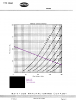
Edit: sorry, I know I'm long-winded and I keep adding stuff, but I've attached the loadline with Vpp, VRMS, and Pout RMS for the current circuit, done the right way using Sodacose's tutorial (Load Line Calculations – wauwatosa tube factory). How does that seem to you guys?
I'm using Grado SR125 (32 ohm) cans with Raphaelite OP5.5K5A OPTs (5.5K: 8 or 32 ohm, 5W) from this seller on eBay (Raphaelite 5W single-ended output transformer OP5.5K5A 6V6 EL84 sealed | eBay). Websites show the primary to be either 5K or 5.5K. I've written to the seller for clarification but am assuming it's 5.5K because they advertise these OPTs for use with 6V6 and EL84 and have two other OPTs designated for those tubes that have 5.5K primaries (also it's in the product name).
Some of the improvements I've been hearing could be due to OPT break-in, but I'm really starting to like these. They do a good job of reproducing detail and other nuance, and are sounding very clear indeed as documented below.
The channels split after the second 100uF cap (it's a JJ 100uF + 100uF). I drew out a schematic of the present state of the circuit (attached) so you can see what I'm working with now.
I don't have an oscilloscope (yet), so I haven't done any sweeps. But the bass response is audibly very good . When I breadboard a change to the circuit, I typically listen for 30-60 minutes through a range of material such as Ella Fitzgerald, Miles Davis, G. Love and Special Sauce, Flaming Lips, and -- the big test -- Mahler's 2nd symphony (and usually several more artists than these). So, a range of acoustic and electronic material with demanding bass and treble passages. In listening, I find frequency extension in both extremes to be perfectly adequate, with very good detail, and of course the midrange is excellent.
Now that I think I've got the circuit set, I decided to experiment with some peripheral elements such as the four 100R grid stopper resistors that connect the signal input to the grid pins. I removed the resistors just to hear what would happen and it was like lifting a vale. Clarity, detail, and transient response were markedly improved, which was surprising to me because I never felt those areas to be lacking.
Many builders warn of oscillation with an underdamped grid on the 5842. I don't know if oscillation is audible, but it certainly sounded good to me without any grid stoppers for about 75 minutes last night.
Edit: sorry, I know I'm long-winded and I keep adding stuff, but I've attached the loadline with Vpp, VRMS, and Pout RMS for the current circuit, done the right way using Sodacose's tutorial (Load Line Calculations – wauwatosa tube factory). How does that seem to you guys?
Attachments
Last edited:
The operating points you posted here don't line up with the load line you posted here.
It could be that the characteristics of your actual tube are far off from the bogey tube used to create the published curves. I guess that's just how it is with these high-gm RF tubes. They're all over the place.
The worst I've seen is 6J52P. I hear 6S34P is also very variable.
Also, in the schematic (here), you show the negative terminal of the input RCA jack in series with a 100k resistor to ground. Then the positive terminal of the RCA jack is directly connected to the 5842 grid, but there's no grid leak resistor drawn from the 5842 grid to ground. Your amp needs a grid leak resistor, or that 5842 isn't likely to last for very long. It might just be drawn wrong, but it's worth checking to make sure.
--
Last edited:
That was the loadline for the 139V/27mA operating point (the second one above), which is the current candidate for the final build. It's difficult to see, but there's a green dot "underneath" the purple line at 139V/27mA, which is the idle op point. I divided the B+ voltage of 149V by the 5.5k primary impedance of the OPT and got 27mA, which is then added to the existing 27mA on the left axis of the chart to get the maximum current (54mA). I then drew a line through those two points and all the way across the graph. Is that not the way to do it?
Ah! My mistake. There is in fact a 100K grid leak resistor. I just drew it in the wrong place and forgot to put the volume pot in the schematic.Also, in the schematic (here), you show the negative terminal of the input RCA jack in series with a 100k resistor to ground. Then the positive terminal of the RCA jack is directly connected to the 5842 grid, but there's no grid leak resistor drawn from the 5842 grid to ground. Your amp needs a grid leak resistor, or that 5842 isn't likely to last for very long. It might just be drawn wrong, but it's worth checking to make sure.
Last edited:
My understanding of how to do a load line for a tube used with a single-ended output transformer (done in MS Paint or a similar raster editor):
1) The 'slope' of the load line is calculated as if for a resistive plate load.
- Take an arbitrary B+ voltage and divide by the primary (load) impedance of your OPT.
Let's say we take 200V (because that's easy to see on the 5842 plate curves graph) and divide that by 5,500 ohms (the primary impedance of your OPT).
200V / 5,500 ohms = 0.03636 A (or 36.4 mA)
2) Draw a floating line from 200V on the 'y' axis (horizontal axis along the bottom) of the plate curves to 36.4mA on the 'x' axis (vertical axis) on the left.
3) Move the floating line you've drawn to the right until it reaches the operating points you've chosen for the tube. Let's say you want the Vp (plate voltage) to be 140V and the Ip (plate current) to be 20mA.
4) Move the floating line from left to right (but NOT up or down) until it intersects the 140V vertical line.
- Follow a horizontal line from that point to the x axis on the left and you will see the predicted Ip.
- Look at the grid voltage curves to see the predicted grid bias voltage.
If the result is that you need a grid bias of -1.8V to bias the tube at Vp = 140V and Ip = 20mA, and you'll be using a cathode bias resistor (Rk), then:
Rk = Vg / Ip
1.8V / 0.02A = 90 ohms
(Those are example numbers I used, not derived from the plate curves. You'll need to use that process to find the correct results from the 5842 plate curves graph.)
I hope that helps.
--
Last edited:
I divided the B+ voltage of 149V by the 5.5k primary impedance of the OPT and got 27mA, which is then added to the existing 27mA on the left axis of the chart to get the maximum current (54mA). I then drew a line through those two points and all the way across the graph.
I'm not sure what you're doing there. Maybe I'm doing it wrong.
What I get at Vp = 149V, using your load line, is:
- The purple line meets the 149V mark on the y axis at about 26mA on the x axis.
- The estimated grid bias is just less than -1.5V, so let's say -1.4V.
Remembering that the value of Rk in ohms = Vg / Ip,
1.4V / 0.026A = 53.846 ohms
56 ohms is the closest standard value.
--
Last edited:
Rongon, I really appreciate the time and effort you've put in to checking my math and graphing, so thank you for that.
I followed your procedure using my chosen op point of 139Vp @ 27.17mA, and it attained similar results to those I got with the procedure described by Sodacose.
Using the 200V arbitrary B+ divided by 5.5K load, I drew a (purple) line from 200V on the Y-axis to 36.4mA on the X-axis. Then I moved the line to the right (but not up or down) until it intersected my operating point of 139V/27mA.
In order to see where the line intersects the X-axis, I made another (red) floating line parallel to it, and then moved it into place so that it was continuous with the purple line. It intersects the X-axis at 52.5mA, which is about 1.5mA below the 54mA in my previous attempt. So the line of this one is just slightly less steep.
I then drew the (green) vertical and horizontal lines from the op point to the 139V and 27mA points on the respective axes.
The Vg-pp value of 2.4V is the same as before, since that point on the graph has not changed. What has changed, though, is the Plate VRMS values owing to the different load line angle.
The results are very similar: 6.2VRMS and 0.03 watts output, as opposed to 6.32VRMS and 0.036 watts output in the previous attempt.
I've attached screenshots of the new and previous attempt for side-by-side comparison.
Actually, Vp is 139V. B+ is 149V. This might be the source of the discrepancy.What I get at Vp = 149V, using your load line
--
I followed your procedure using my chosen op point of 139Vp @ 27.17mA, and it attained similar results to those I got with the procedure described by Sodacose.
Using the 200V arbitrary B+ divided by 5.5K load, I drew a (purple) line from 200V on the Y-axis to 36.4mA on the X-axis. Then I moved the line to the right (but not up or down) until it intersected my operating point of 139V/27mA.
In order to see where the line intersects the X-axis, I made another (red) floating line parallel to it, and then moved it into place so that it was continuous with the purple line. It intersects the X-axis at 52.5mA, which is about 1.5mA below the 54mA in my previous attempt. So the line of this one is just slightly less steep.
I then drew the (green) vertical and horizontal lines from the op point to the 139V and 27mA points on the respective axes.
The Vg-pp value of 2.4V is the same as before, since that point on the graph has not changed. What has changed, though, is the Plate VRMS values owing to the different load line angle.
The results are very similar: 6.2VRMS and 0.03 watts output, as opposed to 6.32VRMS and 0.036 watts output in the previous attempt.
I've attached screenshots of the new and previous attempt for side-by-side comparison.
Attachments

Looks good. In real life I don't think a 5842 can swing all the way down to 0V grid bias.
That would reduce your Vg-pp figure of 2.4V (to 0V).
I'd calculate the Vg-pp to go from the -2.4V grid bias line down to -0.5V, so it would be more like -1.9V. I'd move the operating point to be biased more centrally to that, so more like Vp = 150V, Vg = -1.5V, Ip = 25mA. Funny thing: the Rk would be 60 ohms.
A Vg (grid bias) of -1.2V is likely to have the 5842 drawing grid current much of the time. This can load down signal sources driving it. If you have a volume pot with its wiper connecting to the 5842 grid, you might want to put a DC blocking cap between the wiper and the 5842 grid, so that no DC current is drawn across the pot, eventually causing it to fail (get crackly, audio dropping out).
But this is all tweaking and finessing. As long as it sounds good...
--
- Status
- This old topic is closed. If you want to reopen this topic, contact a moderator using the "Report Post" button.
- Home
- Amplifiers
- Tubes / Valves
- 5842 Headphone Amp