Blocking distortion
Bob Carver lately has been using a SS diode + resistor to a modest neg. V (2X bias V), on the grid side of the coupling cap, to symmetrically load the coupling cap against grid current effects. He called it a DC restorer. If you already have a neg. V around for biasing or a tail CCS, you are all set.
Bob Carver lately has been using a SS diode + resistor to a modest neg. V (2X bias V), on the grid side of the coupling cap, to symmetrically load the coupling cap against grid current effects. He called it a DC restorer. If you already have a neg. V around for biasing or a tail CCS, you are all set.
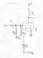
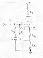
The DC restorer.
-Grid bias is held 1/2 way between the grid conduction and -2x grid bias.
When an AC input causes grid conduction it also causes restorer conduction on the opposite AC peaks. Rr is sized to simulate the +0V grid conduction path resistance, for symmetrical cancelling conduction to the coupling capacitor C.
Attachments
One thing (I don't think I've seen mentioned yet) for the interstage xfmr is that it blocks common mode voltages from a P-P driver. A balancing (ct'd) load inductor could do the same thing for P-P, where DC isolation isn't needed. A CCS tail under a differential driver stage would also block common mode voltages.
AC common mode voltages are a product of symmetrical P-P tube distortion effects, so removing them removes some of the distortions. (some odd harmonics) Bound to have some sonic effect. It doesn't remove all odd harmonics versus the input however.
AC common mode voltages are a product of symmetrical P-P tube distortion effects, so removing them removes some of the distortions. (some odd harmonics) Bound to have some sonic effect. It doesn't remove all odd harmonics versus the input however.
Last edited:
Another thing is, according to Bill Whitlock in his easy to read paper here "Although a transformer cannot have response to 0 Hz or dc, it can have much less phase distortion than a coupling capacitor chosen for the same cutoff frequency."
Important also the way transformer low frequency distortion results in much lower IMD (measured with SMPTE method: 4:1 ratio, 60Hz and 7 KHz) than active circuits having the same amount of THD. About one order of magnitude (10 times) less. This with standard grade steel.....but someone is still worried about hysteresis...
If you are expecting grid current then a transformer may sometimes be the best option. However, the cap is still more ideal as a component - but less appropriate to the circuit situation.45 said:Have you ever measured how much grid current a common EL34 can draw when approaching full modulation (Class AB1)? When a smallish grid current will appear things will be the other way around with the capacitor being anything but ideal or nearby. So one either uses a transformer or proper DC coupled stage that can handle that.
If you are expecting grid current then a transformer may sometimes be the best option. However, the cap is still more ideal as a component - but less appropriate to the circuit situation.
I always expect grid current. Even if one buys super-selected tubes with no grid current until 0V is reached the point where the inversion happens will change during tube life quite significantly and unfortunately there is no way to predict it in individual cases.
If the amp is more powerful than needed it might not be a problem of course but that's subjective...
Important also the way transformer low frequency distortion results in much lower IMD (measured with SMPTE method: 4:1 ratio, 60Hz and 7 KHz) than active circuits having the same amount of THD. About one order of magnitude (10 times) less. This with standard grade steel.....but someone is still worried about hysteresis...
Let's advise people that must use transformers without valves.

More seriously, do you have measurements that support your claim?
I would certainly not advise people to use a 12AT7 to drive a 300B for cancelling 3rd harmonic distortion!?!?!Let's advise people that must use transformers without valves.
More seriously, do you have measurements that support your claim?
Not my claim. Seriously you should read more carefully everything.
Pag.10 of the link above.
I would certainly not advise people to use a 12AT7 to drive a 300B for cancelling 3rd harmonic distortion!?!?!
Some folks use the 6SF5GT, and I do not say anything...
http://www.bartola.co.uk/valves/2017/06/04/6sf5-driver-for-300bgm70813-se-amps/
Not my claim. Seriously you should read more carefully everything.
Pag.10 of the link above.
For virtually all electronic amplifier circuits, there is an approximate relationship between harmonic distortion and SMPTE IM distortion. For example, if an amplifier measured 0.1% THD at 60 Hz at a given operating level, its SMPTE IM distortion would measure about three or four times that, or 0.3% to 0.4% at an equivalent operating level
As both kinds of distortion are level dependent and, obviously, circuit dependent, this universal relationship seems to me misleading, to say the least, that's why I asked you for measurements.
If it were true, measuring just THD should be enough, why bother to measure SMPTE IMD?
For example, the Jensen JT-10KB-D line input transformer has a THD of about 0.03% for a +26 dBu input at 60 Hz.
But, at an equivalent level, its SMPTE IM distortion is only about 0.01% — about a tenth of what it would be for an amplifier having the same THD.
No offense, but this looks like a commercial advertisement.
Anyway, the Jensen JT-10KB-D does not look like having standard grade steel, maybe your standards are higher than mine?
Yes, 150V P-P with very low distortion. The driver is a mosfet source follower.Some folks use the 6SF5GT, and I do not say anything...
http://www.bartola.co.uk/valves/2017/06/04/6sf5-driver-for-300bgm70813-se-amps/
Cancelling 3rd harmonic distortion never heard of it. 2nd harmonic is possible within limits otherwise higher harmonics are boosted up!
As both kinds of distortion are level dependent and, obviously, circuit dependent, this universal relationship seems to me misleading, to say the least, that's why I asked you for measurements.
If it were true, measuring just THD should be enough, why bother to measure SMPTE IMD?
They do not depend on frequency in the same way. That's general and makes the difference.
No offense, but this looks like a commercial advertisement.
Anyway, the Jensen JT-10KB-D does not look like having standard grade steel, maybe your standards are higher than mine?
Steel or nickel it doesn't change the trend. In this case it's nickel because it's for line level, the higher initial permeability of nickel is almost a must and the author speaks of what he knows for sure! The higher distortion of steel is low (negligible) anyway in comparison to typical distortion figures of amplifiers that are mainly caused by non linearity of the active devices & circuits, limited inductance in relation to source impedance (where applicable) etc....
Last edited:
Cancelling 3rd harmonic distortion never heard of it. 2nd harmonic is possible within limits otherwise higher harmonics are boosted up!
Morgan Jones - Valve Amplifiers Fourth Edition - at page 182 shows harmonic distortion cancellation between a common cathode stage and a cathode follower for H2, H3, H4, H5, H6, H7, H8, H9 and H10.
With a mu follower plus a source follower driving the 300B I did obtain, in simulations, a clear reduction in H3 with the ECC81/12AT7, and a little better with the 6GK5, with more linear valves like D3A results was the other way around.
They do not depend on frequency in the same way. That's general and makes the difference.
That does not change the fact that your statement is only supported by a dubious universal relationship and a commercial advertisement published on a book.
Anyway, people use to use a transformer with a driving valve, then you must take into account the distortion of the entire stage, if you like transformers as the filosofal stone, I do not, even more, I hate them and after finish my new amplifier, I will burn the lathe...
!
Maybe you are confusing harmonic cancellation with bootstrapped cathode follower?
The bootstrap consists in splitting the anode resistor of the common cathode in two resistors and connecting a capacitor between the cathode of the cathode follower and the junction of the two anode resistors. This way the cathode follower bootstraps the lower anode resistor which becomes very high in value (kind of current source). So the whole distortion can be reduced.
Bootstrapping is also used in the Mac amps from the transformer exactly to boost the anode resistor to high value so that a smaller resistor value and higher anode current can be used to make the tube work very linearly.
A proper cathode follower will have very low distortion on its own. There is no cancellation.
Never heard of such thing and I don't believe it. Cancelling 2nd harmonic only is already something that has limitations and is always done with stages of the same type.Morgan Jones - Valve Amplifiers Fourth Edition - at page 182 shows harmonic distortion cancellation between a common cathode stage and a cathode follower for H2, H3, H4, H5, H6, H7, H8, H9 and H10.
Maybe you are confusing harmonic cancellation with bootstrapped cathode follower?
The bootstrap consists in splitting the anode resistor of the common cathode in two resistors and connecting a capacitor between the cathode of the cathode follower and the junction of the two anode resistors. This way the cathode follower bootstraps the lower anode resistor which becomes very high in value (kind of current source). So the whole distortion can be reduced.
Bootstrapping is also used in the Mac amps from the transformer exactly to boost the anode resistor to high value so that a smaller resistor value and higher anode current can be used to make the tube work very linearly.
A proper cathode follower will have very low distortion on its own. There is no cancellation.
If you believe it, good for you.With a mu follower plus a source follower driving the 300B I did obtain, in simulations, a clear reduction in H3 with the ECC81/12AT7, and a little better with the 6GK5, with more linear valves like D3A results was the other way around.
Not really! Those Jensen transformers are used in several Jeff Rowland products which indeed have very low IMD.That does not change the fact that your statement is only supported by a dubious universal relationship and a commercial advertisement published on a book.
Who doesn't do that?Anyway, people use to use a transformer with a driving valve, then you must take into account the distortion of the entire stage,
Never heard of such thing and I don't believe it.
Everyday you learn something new, Morgan Jones just confirmed what I saw in simulations.
I am a believer.
As I understand it, distortion cancellation usually cancel H2 at the expense of increasing H3 and higher harmonics. Quoting Morgan Jones page 181 "We can see that full nulling (11.2 kΩ AC load) reduces H2 by 27 dB from 259 dB to 286 dB (0.005%), which is certainly impressive, but at the expense of skewing the distortion spectrum so that H3 is 8 dB higher than H2.". As shown on page 182, at No null, H2 was higher than H3 but with Full null, H2, H5, H6, H7 and THD was reduced but H3, H4, H8, H9 was increased. To me, the resulting non monotonic distortion spectrum at Full null resembles a PP circuit distortion spectrum rather than SE.Morgan Jones - Valve Amplifiers Fourth Edition - at page 182 shows harmonic distortion cancellation between a common cathode stage and a cathode follower for H2, H3, H4, H5, H6, H7, H8, H9 and H10....
H3 cancellation technique interests me very much. So far I have only found the Western Electric Harmonic Balancer/Equalizer such as used in the WE86A and WE92A amplifier for PP circuit. Richard Marsh on the Blowtorch thread somewhere (if I'm not mistaken) once mentioned the H3 cancellation property when Lateral Mosfet follower was used to buffer a tube stage, but without any detail.
Could you elaborate a bit more on your H3 cancellation circuit and finding?
Last edited:
H3 cancellation technique interests me very much. So far I have only found the Western Electric Harmonic Balancer/Equalizer such as used in the WE86A and WE92A amplifier for PP circuit.
I remember that the WE solution is a form of non-linear feedback based on common mode anode current variation caused by odd harmonics. If you search on this forum you should find some more info....
- Status
- This old topic is closed. If you want to reopen this topic, contact a moderator using the "Report Post" button.
- Home
- Amplifiers
- Tubes / Valves
- Theoretical question about interstage transformers